


10. Start the boiler according to the “Start-Up
Instructions” in this manual. Operate the system,
including the pump, boiler and radiation units, for
one hour.
11. Recheck the water level in the expansion tank. If
it exceeds half the tank volume, open the tank to
reduce the water level. Recheck pres sure charge
on diaphragm type tanks.
12. Shut down the entire system and vent all ra di a tion
units and high points in the system.
13. Close the water makeup valve and check the
strainer and pressure reducing valve for sediment
or debris. Reopen the water makeup valve.
14. Verify system pressure with the boiler pres sure
gauge before beginning regular operation.
15. Within three days of start-up, recheck and bleed all
air vents and the expansion tank using these
instructions.
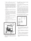
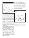
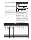
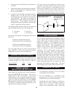
FIG. 47 Installation with a Chilled Water System
Pipe refrigeration systems in parallel. Install duct coil
downstream at the cooling coil. Where the hot water
heat ing boiler is connected to a heating coil located in
the air handling units which may be ex posed to
re frig er a tion air circulation, the boiler pip ing system
must be equipped with flow control valves or other
automatic means to prevent gravity circulation of the
boiler wa ter during the cooling cycle. The coil must be
vented at the high point and hot water from the boiler
must enter the coil at this point. Due to the fast heating
capacity of the boiler, it is not necessary to provide a
ductstat to delay circulator operation. Also, omit
ther mo stat flow checks as the boiler is cold when
heating ther mo stat is satisfied. This provides greater
econ o my over maintaining standby heat.
37
INSTALLATION WITH A CHILLED
WATER SYSTEM
EXPANSION
TANK
CHILLER
BOILER
IN
OUT
SUPPLY
GAS
WATER
SUPPLY
LOW WATER
F
LOW SWITCH
COOLING COIL
HEATING AND
PUMP
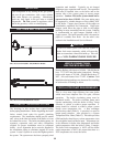
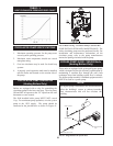
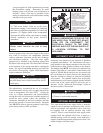
Btu/hr 10°F T 20°F T 30°F T 40°F T 50°F T
Input Output GPM Ft/hd GPM Ft/hd GPM Ft/hd GPM Ft/hd GPM Ft/hd
45,000 36,900 7.4 0.6 3.7 0.2 2.5 0.2 1.9 0.2 -- --
75,000 61,500 12.3 1.3 6.2 0.4 4.1 0.3 3.1 0.2 -- --
90,000 73,800 14.9 1.4 7.4 0.5 5.0 0.3 3.7 0.2 -- --
135,000 110,700 22.3 3.2 11.1 1.2 7.4 0.6 5.6 0.3 -- --
180,000 147,600 29.7 5.1 14.9 1.6 9.9 0.7 7.4 0.4 -- --
215,000 176,300 -- -- 17.0 1.3 11.8 0.8 8.9 0.4 -- --
260,000 213,200 -- -- 21.5 2.1 14.3 0.9 10.7 0.5 -- --
315,000 258,300 -- -- 26.0 4.1 17.3 2.2 13.0 1.3 -- --
360,000 295,200 -- -- 29.7 5.4 19.8 2.5 14.9 1.5 -- --
399,999 327,180 -- -- 33.0 8.1 22.0 3.6 16.5 2.0 13.2 1.7
500,000 410,000 -- -- -- -- 27.6 6.6 20.7 3.5 16.6 2.1
TABLE - N
SYSTEM TEMPERATURE RISE CHART
Based on Boiler Output in Btu/hr