


3 Troubleshooting
42
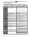
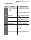
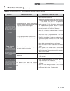
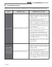
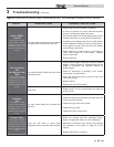
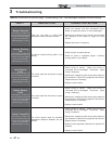
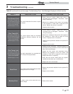
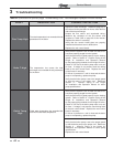
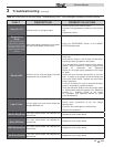
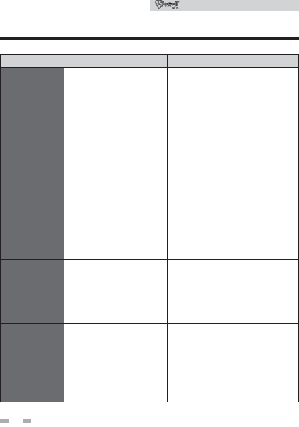
Table 3-4 (continued from previous page) Troubleshooting Chart - Fault Messages Displayed on Boiler Interface
Service Manual
FAULT DESCRIPTION CORRECTIVE ACTION
Sensor Shorted
(will require a manual reset
once the condition has been
corrected. Press the RESET
button on the SMART
SYSTEM
display to reset.)
Either the inlet water or outlet water
temperature sensor has been shorted.
• Check the sensors and their associated wiring.
Repair or replace the sensor or wiring if damaged.
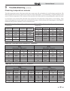
• Measure the resistance of the sensors and compare
the resistance to the tables on page 35 of this
manual.
• Replace the sensor if necessary.
Louver Proving
Sw
(will require a manual reset
once the condition has been
corrected. Press the RESET
button on the SMART
SYSTEM
display to reset.)
An optional remote proving switch is not
making.
• Check function of remote devices.
• Check for loose or misplaced jumper if auxiliary
proving switch is not installed.
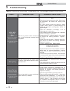
Inlet Sensor
Fault
(will require a manual reset
once the condition has been
corrected. Press the RESET
button on the SMART
SYSTEM
display to reset.)
The control reads the inlet sensor as open
or shorted.
• Check wiring to sensor. Make sure wiring is
connected and not damaged. Reconnect / repair
wiring if necessary.
• Measure the resistance of the sensor and compare to
the resistance in Table 3-2A on page 35 of this manual.
Replace sensor if necessary.
• Replace control module.
Outlet Sensor
Fault
(will require a manual reset
once the condition has been
corrected. Press the RESET
button on the SMART
SYSTEM
display to reset.)
The control reads the inlet sensor as open
or shorted.
• Check wiring to sensor. Make sure wiring is
connected and not damaged. Reconnect / repair
wiring if necessary.
• Measure the resistance of the sensor and compare to
the resistance in Table 3-2C on page 35 of this manual.
Replace sensor if necessary.
• Replace control module.
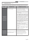
Outlet Temp Diff
(will require a manual reset
once the condition has been
corrected. Press the RESET
button on the SMART
SYSTEM
display to reset.)
The control module reads an excessive
temperature difference between the two
sensors.
• Check wiring to sensor. Make sure wiring is
connected and not damaged. Reconnect / repair
wiring if necessary.
• Measure the resistance of the sensor and compare to
the resistance in Table 3-2C on page 35 of this manual.
Replace sensor if necessary.
• Restore control parameter defaults from optional PC
software.
• Replace control module.