


24
1 Service
Service Manual
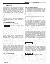
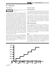
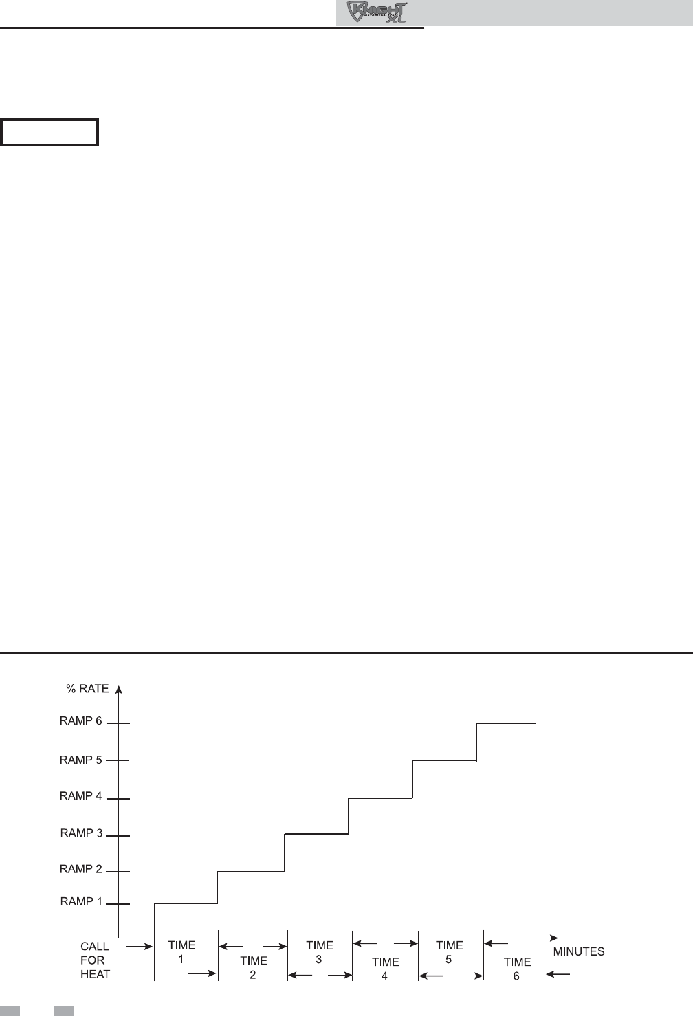
Figure 1-2 Ramp Delay Interval
Control modes
Controlling Sensor
The SH controlling sensor parameter selects the sensor the
control will use to regulate the boiler firing rate. This parameter
is adjustable by the installer by accessing the Controlling Sensor
parameter. The sensor selections are as follows: The outlet
sensor regulates the firing rate based on the outlet water
temperature of the boiler and the inlet sensor regulates the
firing rate based on the inlet water temperature of the boiler.
If the outlet sensor is selected, and the optional system supply
sensor is connected, the control will regulate the firing rate
based on the system supply sensor temperature. The default
sensor is the Outlet Sensor.
BMS Thermostat Input
When controlling the boiler through the 0 - 10V BMS input or
through ModBus, the boiler can be enabled one of two ways.
With the BMS Thermostat Input parameter set to ACTIVE,
the boiler will be enabled by closing the Heat/Loop Demand 1
input. When set to INACTIVE, the boiler will be enabled by the
voltage level on the 0 - 10V input (in the case of 0 - 10V BMS
control), or the 0 - 10V input value received through ModBus.
The default value is INACTIVE.
BMS
The set point or modulation of the boiler may be controlled
through the 0 - 10V BMS input or through ModBus. When the
BMS parameter is set to INACTIVE, the 0 - 10V input will be
ignored. When set to ACTIVE, the set point or modulation will
be controlled by the voltage on the 0 - 10V input (in the case
of 0 - 10V BMS control), or the 0 - 10V input value received
through ModBus. The default value is INACTIVE.
When finished, the installer can press the RIGHT SELECT
[SAVE] key to store the new settings, or the LEFT SELECT
[EXIT] key to return to the Anti-Cycling parameter list
without saving the changes. The delay value can be set
between 0 minutes and 20 minutes. The limit value can be
set between 0% and 100%.
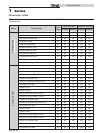
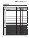
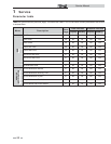
Ramp Settings
The SMART SYSTEM control can be programmed to limit
the firing rate for a fixed period of time at the start of a
space heating demand. There are six (6) possible limits,
each with their own time delay. The first limit applies as
soon as the burner starts. Once its time delay expires, the
second limit is applied and its timer begins. The control
steps through these limits until the 6th (sixth) limit expires.
Note, however, that the 6th limit will also limit the rate for
the rest of that heat demand. The installer can adjust the
firing limits and time delays by accessing the Ramp Settings
parameter. Once this parameter is selected, the screen will
show the step number, the time delay for that step and the
limit value corresponding with that step. If the installer
wishes to adjust one of the values in that step, he can press
the NAVIGATION dial until the value he wishes to change
is flashing. The installer can then rotate the NAVIGATION
dial to adjust that value. If the installer presses the RIGHT
SELECT [SAVE] key while the limit value is flashing,
the step value will flash again. The installer can then
select the next step and adjust the delay and limit values
corresponding with that step.
Please note that the brackets ([]) denote
screen status.
NOTICE