


3 Troubleshooting (continued)
41
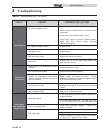
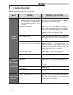
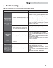
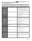
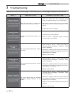
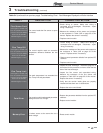
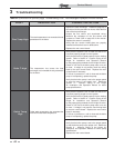
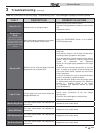
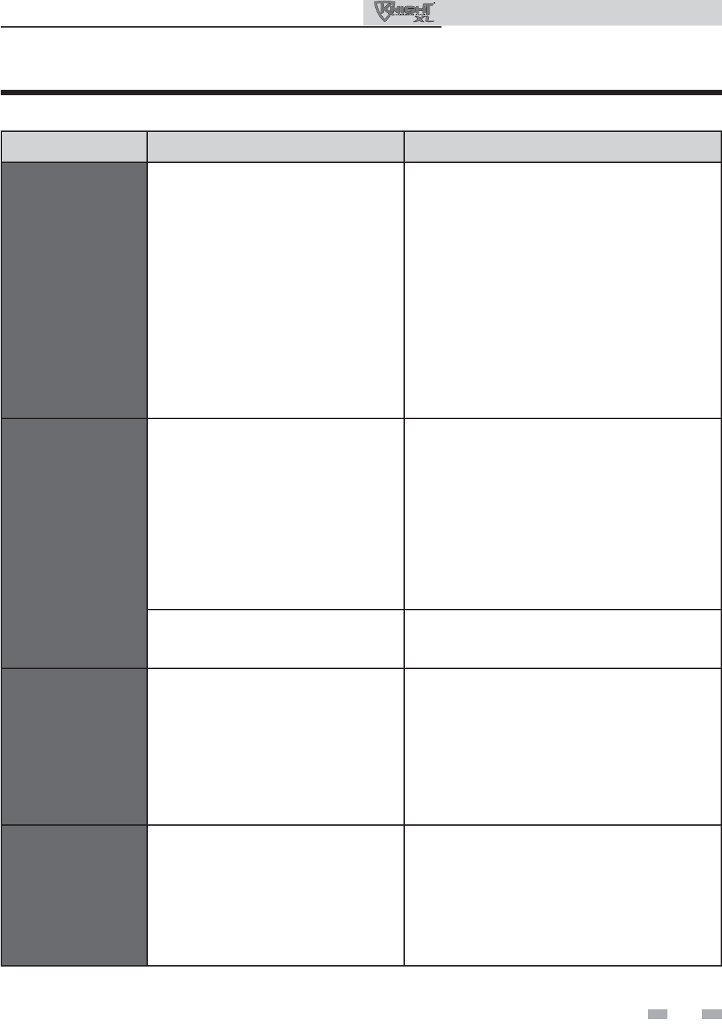
Table 3-4 (continued from previous page) Troubleshooting Chart - Fault Messages Displayed on Boiler Interface
Service Manual
FAULT DESCRIPTION CORRECTIVE ACTION
Outlet MRHL
(cont’d)
(will require a manual
reset once the condition
has been corrected. Press
the RESET button on the
SMART SYSTEM
display
to reset.)
The outlet water temperature has exceeded
the setting of the manual reset high limit.
• Replace the main control board if necessary.
• If 120 vac is present on a call for heat and the boiler
pump is not operating, replace the pump.
• If the system pump is a variable speed pump, ensure
that the system flow is not less than the boiler flow.
• If operating on something other than an outlet sensor,
check temperature setting of the main control board.
• If the optional manual reset high limit has tripped,
check setting of the device.
• Check resistance of water sensors and compare to
Table 3-2A on page 35 of this manual. Replace
sensor if necessary.
• Replace high limit.
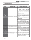
Fan Low/High
OR
Fan Speed Low/
High
(will require a manual
reset once the condition
has been corrected. Press
the RESET button on the
SMART SYSTEM
display
to reset.)
The actual fan RPM is 30% lower than what
is being called for.
• Vent/air intake lengths exceed the maximum allowed
lengths. Refer to Section 3 - General Venting of the
Knight XL Installation and Operation Manual for
proper lengths.
• Check for obstruction or blockage in the vent/air
intake pipes or at terminations.
• Check the wiring connections at the fan and at the
main control board.
• Replace the fan.
• Replace the main control board.
Blown fuse.
• Replace fuse F2 on the control board, see page 33
of this manual.
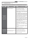
GV/Relay
Fail
(will require a manual
reset once the condition
has been corrected. Press
the RESET button on the
SMART SYSTEM
display
to reset.)
The main control board did not detect the
gas valve.
• Check wiring harness connection at the gas valve and
at the main control board.
• Replace the gas valve wire harness.
• Replace the gas valve.
• Replace the main control board.
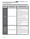
Sensor Open
(will require a manual
reset once the condition
has been corrected. Press
the RESET button on the
SMART SYSTEM
display
to reset.)
Either the inlet water or outlet water
temperature sensor has been disconnected.
• Check the sensors and their associated wiring.
Repair or replace the sensor or wiring if damaged.
• Measure the resistance of the sensors and compare
the resistance to the tables on page 35 of this
manual.
• Replace the sensor if necessary.