


2 Maintenance
32
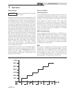
Check flame signal
1. At high fire the flame signal shown on the display should
be at least 10 microamps.
2. A lower flame signal may indicate a fouled or damaged
flame sense electrode. If cleaning the flame sense electrode
does not improve, ground wiring is in good condition,
and ground continuity is satisfactory, replace the flame
sense electrode.
3. See Section 3 - Troubleshooting in this manual for other
procedures to deal with low flame signal.
Review with owner
1. Review the Knight XL User’s Information Manual with
the owner.
2. Emphasize the need to perform the maintenance schedule
specified in the Knight XL User’s Information Manual
(and in this manual as well).
3. Remind the owner of the need to call a licensed contractor
should the boiler or system exhibit any unusual behavior.
4. Remind the owner to follow the proper shutdown
procedure and to schedule an annual start-up at the
beginning of the next heating season.
The boiler contains ceramic fiber
materials. Use care when handling these
materials per instructions on page 3 of
this manual. Failure to comply could
result in severe personal injury.
ƽ WARNING
Cleaning boiler heat exchanger
For recommended materials; including brush, appropriate
extension(s), refractory cover, and detailed instructions see
Table 2-2 - Heat Exchanger Cleaning Kits.
1. Shut down boiler:
• Follow the “To Turn Off Gas to Appliance” instructions
for the boiler in Section 10 - Startup of the Installation
and Operation Manual.
• Do not drain the boiler unless it will be exposed to
freezing temperatures. If using freeze prevention fluid
in system, do not drain.
2. Allow time for the boiler to cool to room temperature if
it has been firing.
3. Remove the nuts securing the heat exchanger access cover
to the heat exchanger and set aside.
4. Remove the heat exchanger access cover, burner, and
gas/air arm assembly.
7. Brush the heat exchanger while dry using a nylon bristle
brush. Caution: DO NOT use a metal brush. Re-vacuum
the heat exchanger.
8. Finish cleaning using a clean cloth dampened with warm
water. Rinse out debris with a low pressure water supply.
9. Allow the heat exchanger to thoroughly dry.
10. Remove the field supplied rear refractory cover from the
back of the combustion chamber of the heat exchanger and
reassemble.
11. Close isolation valves on piping to isolate boiler from
system. Attach a hose to the boiler drain and flush boiler
thoroughly with clean water by using purging valves to
allow water to flow through the water make-up line to the
boiler.
12. Perform start-up and check-out procedures in the Check
Flame and Combustion - Section 10 - Startup of the
Installation and Operation Manual.
13. Replace the access cover and restore boiler to operation.
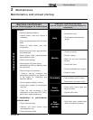
Table 2-2 Heat Exchanger Cleaning Kits
Model
Kit
Number
Part
Number
Component
Description
400 KIT30063
CTN20005 Rear Refractory Cover
MSC20083* Nylon 4" Wheel Brush*
MSC20084 3mm Allen Wrench
MSC20086 1/4" x 24" Drill Extension
501 - 801 KIT30064
CTN20005 Rear Refractory Cover
MSC20083* Nylon 4" Wheel Brush*
MSC20085 1/4" x 12" Drill Extension
MSC20086 1/4" x 24" Drill Extension
* Do NOT use a metal brush. Only use
the kit provided brush or an equivalent
replacement nylon brush.
ƽ CAUTION
Service Manual
5. Remove the condensate hose from the heat exchanger
end. Connect a field supplied 3/4” diameter hose to
a drain pan. Using field supplied means, cover the
refractory in the back of the combustion chamber of the
heat exchanger.
6. Use a vacuum cleaner to remove any accumulation on the
boiler heating surfaces. Do not use any solvent.
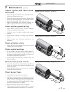
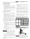
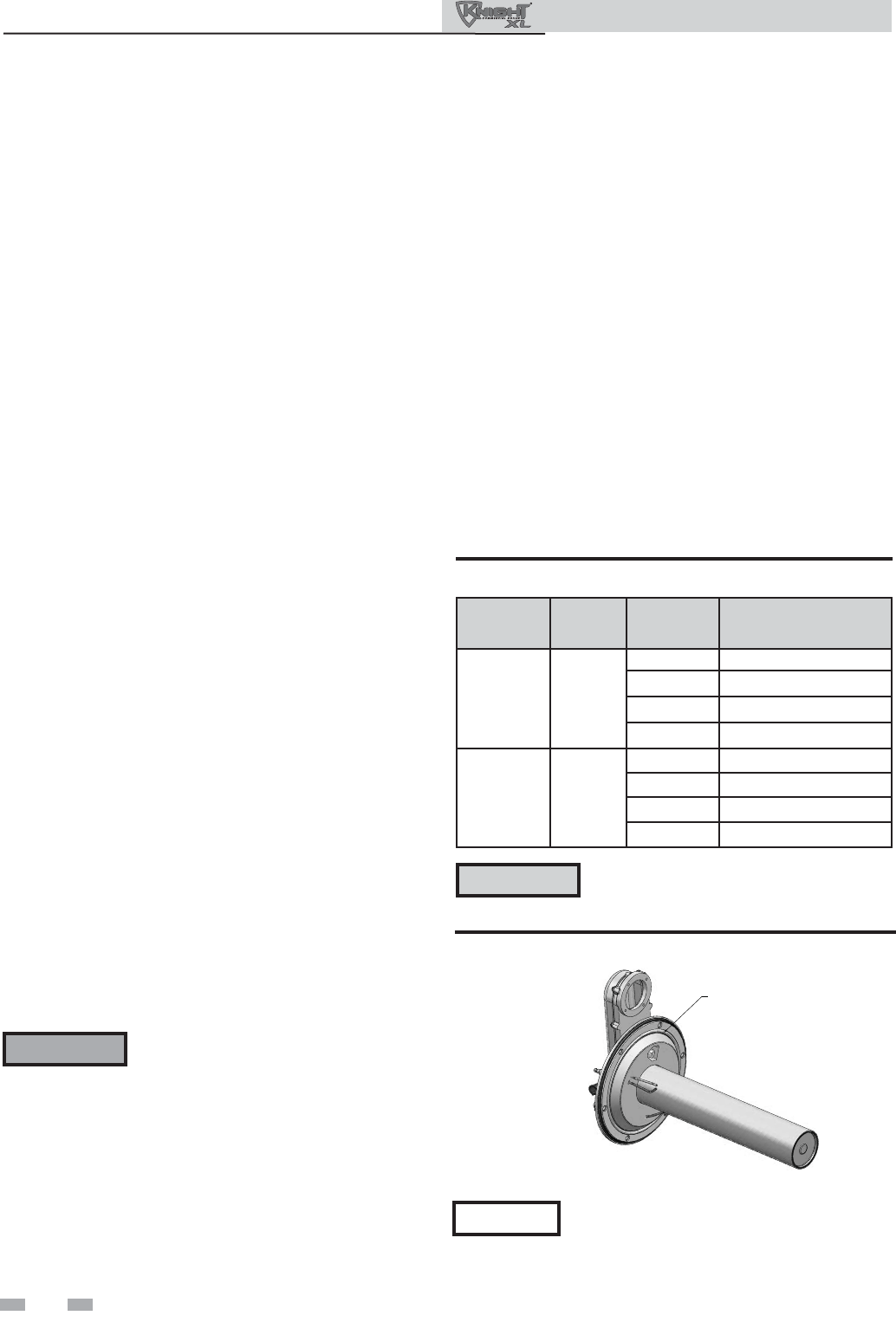
NOTICE
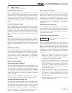
Rope gasket is intended for sealing combustion
(FIG. 2-5). If damaged DO NOT reuse, the
heat exchanger door must be replaced. Consult
factory for replacement heat exchanger door
(kit WTR3080 and WTR3086).
ROPE GASKET
CAUTION: IF GASKET IS DAMAGED
DO NOT REUSE, THE HEAT EXCHANGER DOOR
MUST BE REPLACED.
Figure 2-5 Rope Gasket - Heat Exchanger Door