


25
1 Service (continued)
Service Manual
ModBus
When BMS is set to ACTIVE (see BMS Active / Inactive)
and the boiler is being controlled through ModBus, set
ModBus parameter to ACTIVE. Otherwise, set the ModBus
parameter to INACTIVE. Note that the boiler can still
be monitored by ModBus with this parameter set to
INACTIVE. The default value is INACTIVE.
ModBus T/O
The amount of time the unit controls will wait to receive
a communication string from the BMS controller before
reverting back to its own internal parameters. This
parameter is adjustable by the installer by accessing the
ModBus T/O parameter. The adjustment range of this
parameter is 5 seconds to 2 minutes. The default value is
10 seconds.
Cascade Address
The boiler designated as the Leader needs to be programmed
with address 0. All the Member boilers require addresses
from 1 to 7, and the addresses must be different for each
Member. The addresses can be in any order, regardless
of the order in which the units are wired together. This
parameter is adjustable by the installer by accessing the
Cascade Address parameter. The outdoor air (if used) and
system supply sensor must be connected to the Leader
boiler. The default address is 1.
If installing the boilers in an existing system, the new
boilers should be programmed as the Leader and/or the
higher number addresses.
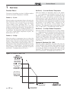
Cascade Type (L/L / EFF)
There are two (2) options for the way a Cascade divides the
load between its heaters. The first is Lead/Lag, designated
as L/L in the menu. This method is used when it is desired
to have the least amount of total flow through the boilers.
This method will modulate the last two (2) boilers. This
provides for smooth transitions when a boiler turns on or
off. When the last boiler reaches 100% and the calculated
load is still increasing, it will start the next boiler at 20%
and reduce the previous boiler to 80%, thus eliminating
the sudden jump in total output of the Cascade. When the
calculated load is decreasing and the last boiler gets down
to 20% fire, it will hold it there and start lowering the firing
rate on the next-to-last boiler. When the next-to-last boiler
reaches 20%, it will turn the last boiler off and raise the
rate of the next-to-last boiler to 40%, thus eliminating the
sudden drop in total output of the Cascade.
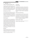
The other Cascade divider method is Efficiency
Optimization, designated as EFF in the menu. This
method is used, as the name implies, when it is desired
to have the most efficient system. When the first boiler
reaches a certain rate (default = 90%), it lowers its rate
to 45% and turns on the next boiler at 45%. The two (2)
boilers then modulate at the same rate.
As the calculated load increases further and both boilers ramp
up to 90%, it lowers the rate of the first two (2) boilers to 60%
and brings the next boiler on at 60%. The three (3) boilers
then modulate together. As the calculated load decreases, the
boilers will reach a lower threshold (default = 30%), at which
time the last boiler (the third in our example) will turn off and
the Cascade will increase the rates of the remaining boilers to
provide the equivalent total output as before ((3 x 30%) / 2 =
45% in our example).
Maximum Cascade Set Point
This parameter determines the set point used by the individual
boilers in a Cascade. When a boiler is commanded to fire by
the Leader boiler, it will attempt to achieve this temperature at
its outlet. The Leader boiler will limit the modulation of the
last boiler to fire in order to hold the temperature at the system
supply sensor to the user set point. If any of the boiler outlet
temperatures reach the maximum cascade set point, the boiler
will then modulate down on its own in order to keep its outlet
temperature within the maximum cascade set point. Therefore,
this parameter can be used to limit the outlet temperatures of
all the boilers in a Cascade. Note that this parameter does
not apply when the boiler is heating an indirect DHW tank.
This parameter is adjustable by the installer by accessing the
Maximum Cascade Set Point parameter. The temperature
range of this parameter is 32° (0°C) to 190°F (88°C). The
default maximum cascade set point is 185°F (85°C).
Cascade Offset
This parameter determines how much the temperature must
go above set point before the lead boiler will turn off. This
parameter can be adjusted by the installer by accessing the
Cascade Offset parameter. The temperature range of this
parameter is 0° to 20°F (11°C) The default value is 10°F (6°C).
Cascade Differential
This parameter determines how much the temperature must
go below the turn off temperature (Set point + Offset) before
the lead boiler turns on. This parameter can be adjusted by the
installer by accessing the Cascade Differential parameter. The
temperature range of this parameter is 0°F to 60°F (33°C) The
default value is 20°F (11°C).
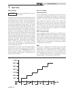
Minimum On/Off Time
In order to prevent units in a Cascade from short cycling,
this parameter defines the minimum ON and OFF time for
each unit. The installer can adjust this time by accessing the
Minimum On/Off Time parameter. The minimum setting is 0
seconds and the maximum setting is 10 minutes. The default
is 30 seconds.
Minimum Next On Time
In order to reduce the risk of temperature overshoot with
a Cascade, this parameter defines the minimum time delay
from starting one unit until the next unit may be started. The
installer can adjust this time delay by accessing the Minimum
Next On Time parameter. The minimum setting is 0 minutes
and the maximum setting is 10 minutes. The default is 60
seconds.