


2 Maintenance
32
Service Manual
Test low water flow conditions
NOTICE
This test is to be carried out once the
Knight XL boiler is completely piped
in with adequate gas and water flow.
Once the test is completed, ensure
that the isolation valve is opened up to
allow full water flow.
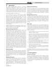
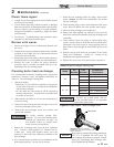
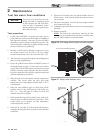
Figure 2-7 Adjust outlet isolation valve
Test procedure
1. Set the [SH1 SETPOINT:] set point to the max user set
point (reference Section 10 of the Knight XL Installation
and Operation Manual). Max user set point will allow
the boiler to operate without reaching this set point. The
boiler will require a load large enough to dissipate a large
portion of the heat it is generating.
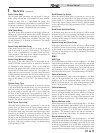
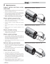
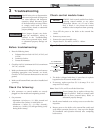
2. Simulate a call for heat by placing a jumper wire across
the enable contacts #19 and 20 on the low voltage
terminal strip located at the rear of the unit (FIG. 2-6).
3. Allow the unit to progress through its normal diagnostics
and pre-purge programming.
4. Locate the pinhole button below the RESET button on
the display board (see page 7). Insert a thin wire (such as
a paper clip) into the hole and press the button once and
hold for 5 seconds to place the boiler into Service Mode.
In Service Mode the boiler will fire at ignition speed and
will then modulate up to full fire.
5. Allow the unit to fire and operate until the temperatures
stabilize. This occurs when the inlet and outlet
temperatures are rising together and the Delta T (ࣼ T)
is maintained.
6. When the unit stabilizes, begin to slowly shut off the
isolation valve on the outlet piping of the boiler (see
FIG. 2-7). This will begin to restrict the flow and
simulate a low flow condition.
7. While slowly shutting off the isolation valve, refer to the
Status Screens to watch the behavior of the boiler. These
screens allow you to monitor the inlet temperature,
outlet temperature, and ࣼT.
8. When the ࣼ T reaches 55˚F, the control will attempt to
modulate the firing rate down to protect it from low flow
conditions.
ADJUST OUTLET
ISOLATION VALVE
ONLY
IMG00098
9. When the ࣼT reaches 60°F, the control module will turn
off the burner. If the control module shuts down, the test
was successful.
10. Disconnect the jumper wire from the low voltage terminal
strip connected in Step 2.
11. Completely open the isolation valve on the outlet piping of
the boiler.
12. Resume operation.
NOTE: This lockout is a soft lockout. Once the ࣼ T has
decreased to an acceptable level and there is a call for heat,
the unit will fire again to meet the demand.
Figure 2-6 Low voltage terminal strip and enable contacts
LOW VOLTAGE CONNECTION BOARD
IMG00103
ENABLE
CONTACTS