


1 Service (continued)
Service Manual
BMS
The set point or modulation of the boiler may be controlled
through the 0 - 10V BMS input or through ModBus. When the
BMS parameter is set to INACTIVE, the 0 - 10V input will be
ignored. When set to ACTIVE, the set point or modulation will
be controlled by the voltage on the 0 - 10V input (in the case
of 0 - 10V BMS control), or the 0 - 10V input value received
through ModBus. The default value is INACTIVE.
ModBus
When BMS is set to ACTIVE (see BMS Active / Inactive) and
the boiler is being controlled through ModBus, set ModBus
parameter to ACTIVE. Otherwise, set the ModBus parameter
to INACTIVE. Note that the boiler can still be monitored by
ModBus with this parameter set to INACTIVE. The default
value is INACTIVE.
ModBus T/O
The amount of time the unit controls will wait to receive
a communication string from the BMS controller before
reverting back to its own internal parameters. This parameter
is adjustable by the installer by accessing the ModBus T/O
parameter. The adjustment range of this parameter is 5 seconds
to 2 minutes. The default value is 10 seconds.
Cascade Address
The boiler designated as the Leader needs to be programmed
with address 0. All the Member boilers require addresses from
1 to 7, and the addresses must be different for each Member.
The addresses can be in any order, regardless of the order in
which the units are wired together. This parameter is adjustable
by the installer by accessing the Cascade Address parameter.
The outdoor air (if used) and system supply sensor must be
connected to the Leader boiler. The default address is 1.
If installing the boilers in an existing system, the new boilers
should be programmed as the Leader and/or the higher number
addresses.
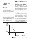
Cascade Type (L/L / EFF)
There are two (2) options for the way a Cascade divides the load
between its heaters. The first is Lead/Lag, designated as L/L in
the menu. This method is used when it is desired to have the
least amount of total flow through the boilers. This method
will modulate the last two (2) boilers. This provides for smooth
transitions when a boiler turns on or off. When the last boiler
reaches 100% and the calculated load is still increasing, it will
start the next boiler at 20% and reduce the previous boiler
to 80%, thus eliminating the sudden jump in total output
of the Cascade. When the calculated load is decreasing and
the last boiler gets down to 20% fire, it will hold it there and
start lowering the firing rate on the next-to-last boiler. When
the next-to-last boiler reaches 20%, it will turn the last boiler
off and raise the rate of the next-to-last boiler to 40%, thus
eliminating the sudden drop in total output of the Cascade.
When finished, the installer can press the RIGHT SELECT
[SAVE] key to store the new settings, or the LEFT SELECT
[EXIT] key to return to the Anti-Cycling parameter list
without saving the changes. The delay value can be set between
0 minutes and 20 minutes. The limit value can be set between
0% and 100%.
Control modes
Controlling Sensor
The SH controlling sensor parameter selects the sensor the
control will use to regulate the boiler firing rate. This parameter
is adjustable by the installer by accessing the Controlling Sensor
parameter. The sensor selections are as follows: The outlet
sensor regulates the firing rate based on the outlet water
temperature of the boiler and the inlet sensor regulates the
firing rate based on the inlet water temperature of the boiler.
If the outlet sensor is selected, and the optional system supply
sensor is connected, the control will regulate the firing rate
based on the system supply sensor temperature. The default
sensor is the Outlet Sensor.
BMS Thermostat Input
When controlling the boiler through the 0 - 10V BMS input or
through ModBus, the boiler can be enabled one of two ways.
With the BMS Thermostat Input parameter set to ACTIVE,
the boiler will be enabled by closing the Heat/Loop Demand 1
input. When set to INACTIVE, the boiler will be enabled by
the voltage level on the 0 - 10V input (in the case of 0 - 10V
BMS control), or the 0 - 10V input value received through
ModBus. The default value is INACTIVE.
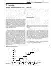
Ramp Settings
The SMART SYSTEM control can be programmed to limit the
firing rate for a fixed period of time at the start of a space heating
demand. There are six (6) possible limits, each with their own
time delay. The first limit applies as soon as the burner starts.
Once its time delay expires, the second limit is applied and its
timer begins. The control steps through these limits until the
6th (sixth) limit expires. Note, however, that the 6th limit will
also limit the rate for the rest of that heat demand. The installer
can adjust the firing limits and time delays by accessing the
Ramp Settings parameter. Once this parameter is selected, the
screen will show the step number, the time delay for that step
and the limit value corresponding with that step. If the installer
wishes to adjust one of the values in that step, he can press
the NAVIGATION dial until the value he wishes to change is
flashing. The installer can then rotate the NAVIGATION dial
to adjust that value. If the installer presses the RIGHT SELECT
[SAVE] key while the limit value is flashing, the step value will
flash again. The installer can then select the next step and adjust
the delay and limit values corresponding with that step.
Please note that the brackets ([]) denote
screen status.
NOTICE
23