


24
1 Service
Service Manual
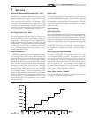
The other Cascade divider method is Efficiency
Optimization, designated as EFF in the menu. This
method is used, as the name implies, when it is desired
to have the most efficient system. When the first boiler
reaches a certain rate (default = 90%), it lowers its rate
to 45% and turns on the next boiler at 45%. The two (2)
boilers then modulate at the same rate.
As the calculated load increases further and both boilers
ramp up to 90%, it lowers the rate of the first two (2)
boilers to 60% and brings the next boiler on at 60%.
The three (3) boilers then modulate together. As the
calculated load decreases, the boilers will reach a lower
threshold (default = 30%), at which time the last boiler
(the third in our example) will turn off and the Cascade
will increase the rates of the remaining boilers to provide
the equivalent total output as before ((3 x 30%) / 2 = 45%
in our example).
Efficiency optimization is automatically selected when
boilers of different sizes are programmed into the Leader
control (see Boiler Size on this page).
Maximum Cascade Set Point
This parameter determines the set point used by the
individual boilers in a Cascade when a system sensor
is connected to the Leader boiler. When a boiler is
commanded to fire by the Leader boiler, it will attempt to
achieve this temperature at its outlet. The Leader boiler
will limit the modulation of the last boiler to fire in order
to hold the temperature at the system supply sensor to
the user set point. If any of the boiler outlet temperatures
reach the maximum cascade set point, the boiler will
then modulate down on its own in order to keep its
outlet temperature within the maximum cascade set point.
Therefore, this parameter can be used to limit the outlet
temperatures of all the boilers in a Cascade. Note that
this parameter does not apply when the boiler is heating
an indirect DHW tank. This parameter is adjustable by
the installer by accessing the Maximum Cascade Set Point
parameter. The temperature range of this parameter is 32°
(0°C) to 190°F (88°C). The default maximum cascade set
point is 185°F (85°C).
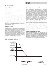
Cascade Offset
This parameter determines how much the temperature
must go above set point before the lead boiler will turn off.
This parameter can be adjusted by the installer by accessing
the Cascade Offset parameter. The temperature range of
this parameter is 0° to 20°F (11°C) The default value is
10°F (6°C).
Cascade Differential
This parameter determines how much the temperature
must go below the turn off temperature (Set point +
Offset) before the lead boiler turns on. This parameter
can be adjusted by the installer by accessing the Cascade
Differential parameter. The temperature range of this
parameter is 0°F to 60°F (33°C) The default value is 20°F
(11°C).
Minimum On/Off Time
In order to prevent units in a Cascade from short cycling,
this parameter defines the minimum ON and OFF time for
each unit. The installer can adjust this time by accessing the
Minimum On/Off Time parameter. The minimum setting is 0
seconds and the maximum setting is 10 minutes. The default
is 30 seconds.
Minimum Next On Time
In order to reduce the risk of temperature overshoot with
a Cascade, this parameter defines the minimum time delay
from starting one unit until the next unit may be started. The
installer can adjust this time delay by accessing the Minimum
Next On Time parameter. The minimum setting is 0 minutes
and the maximum setting is 10 minutes. The default is 60
seconds.
Boiler Size
When boilers of different sizes are connected together in a
Cascade, the Leader boiler has to know the size of each boiler
in that Cascade. The Boiler Size parameters allow the installer
to program the size based on the Cascade address. This screen
shows the Cascade address and the size of the boiler with that
address (in BTU/hr):
1. When the Boiler Size screen is first accessed, Cascade
Address 0 (Leader) is shown.
2. Press the NAVIGATION dial to access the first digit of the
boiler size. Rotate the NAVIGATION dial to adjust the
first digit. To access the next digit, press the NAVIGATION
dial again. Continue this process until the correct boiler
size (to the nearest 1000 BTU/hr) is shown. Press the
RIGHT SELECT [SAVE] key.
3. Rotate the NAVIGATION dial to select the address of the
next boiler in the Cascade. Repeat Step 2.
4. Once the size of the last boiler in the Cascade has been
entered and saved, press the LEFT SELECT [EXIT] key to
return to the Control Modes menu.
5. If no other parameters are to be adjusted, press the RIGHT
SELECT [HOME] key to save the new settings and return
to the Status screens.
The SMART SYSTEM control automatically uses the Efficiency
Optimization Cascade type when controlling boilers of different
sizes.
Circulation pumps
System Pump Delay
The system pump delay parameter sets the length of time the
system pump (if connected) will run after a SH demand has
been satisfied. This parameter is adjustable by the installer by
accessing the System Pump Delay parameter. The time range
for this parameter is 1 second to 40 minutes. The default time
is 30 seconds.