


Installation & Operation Manual
47
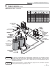
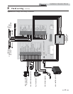
7 Gas connections (continued)
Gas pressure
The gas pressure must remain between 4 inches w.c. (natural),
8 inches w.c. (LP) minimum and 14 inches w.c. (natural and
LP) maximum during stand-by (static) mode and while in
operating (dynamic) mode. If an in-line regulator is used, it
must be a minimum of 10 feet from the Armor water heater. It
is very important that the gas line is properly purged by the gas
supplier or utility company. Failure to properly purge the lines
or improper line sizing, will result in ignition failure.
The problem is especially noticeable in NEW LP installations
and also in empty tank situations. This can also occur when
a utility company shuts off service to an area to provide
maintenance to their lines.
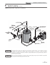
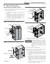
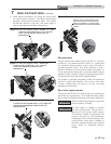
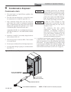
DETAIL
LOOSEN THE SET SCREW ONE (1) FULL TURN AND
PLACE THE MANOMETER TUBING OVER THE
PRESSURE TAP
Figure 7-6 Inlet Gas Supply Check - Models 151 - 286
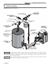
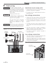
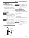
DETAIL
LOOSEN THE SET SCREW ONE (1) FULL TURN AND
PLACE THE MANOMETER TUBING OVER THE
PRESSURE TAP
Figure 7-7 Inlet Gas Supply Check - Model 400
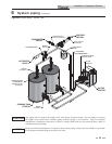
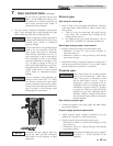
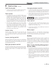
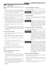
DETAIL
LOOSEN THE SET SCREW ONE (1) FULL TURN AND
PLACE THE MANOMETER TUBING OVER THE
PRESSURE TAP
Figure 7-8 Inlet Gas Supply Check - Model 501
DO NOT adjust or attempt to measure
gas valve outlet pressure. The gas valve is
factory-set for the correct outlet pressure.
This setting is suitable for natural gas and
propane, requiring no field adjustment.
Attempting to alter or measure the gas valve
outlet pressure could result in damage to
the valve, causing potential severe personal
injury, death, or substantial property
damage.
Failure to follow all precautions could result
in fire, explosion, or death!
ƽ WARNING
ƽ WARNING
Gas valve replacement
The gas valve MUST NOT be replaced with a conventional gas
valve under any circumstances. As an additional safety feature,
this gas valve has a flanged connection to the venturi and blower.
17. Check burner performance by cycling the system while
you observe burner response. The burner should ignite
promptly. Flame pattern should be stable. Turn system
off and allow burner to cool, then cycle burner again to
ensure proper ignition and flame characteristics.
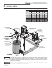
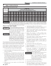
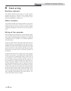
DETAIL
REMOVE THE 1/8” (3 MM) PIPE PLUG ON
THE INLET FLANGE TO THE VALVE AND
INSTALL A SUITABLE 1/8” (3 MM) FITTING
(FIELD SUPPLIED) FOR THE MANOMETER
TUBING.
Figure 7-9 Inlet Gas Supply Check - Models 601 - 801