


Installation & Operation Manual
49
8 Field wiring (continued)
Tank thermostat
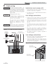
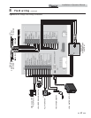
1. Connect the tank thermostats (isolated contact only) to
the tank thermostat contacts as shown in FIG. 8-3.
Tank sensor
1. By installing a tank sensor, the SMART SYSTEM control
can perform the tank thermostat function. The SMART
SYSTEM control automatically detects the presence of
this sensor and generates a DHW call for heat when
the tank temperature drops 6°F (3°C) below the tank
set point and finishes the call for heat when the tank
temperature reaches 3°F (1.5°C) above the tank set point.
2. The tank sensor TST20015 is the only sensor suitable
for use with the SMART SYSTEM control. Connect the
sensor leads to the Tank Sensor terminals on the Low
Voltage Connection Board (FIG. 8-3). Consult the tank
manufacturer for application and performance when
used with any other indirect tank.
Low gas pressure switch
1. If a switch is provided to detect low gas pressure, remove the
jumper wire from the terminals on the connection board
and connect them to its normally open contacts (FIG. 8-3).
2. If both a high and low gas pressure switch are used, connect
their respective contacts in series, and connect them to the
terminals on the connection board (FIG. 8-3).
Flow switch
1. A flow switch is used to guarantee flow through the water
heater before allowing it to fire. The flow switch must be
installed at the water heater outlet.
2. Connect these terminals to the normally open contacts on
the flow switch (FIG. 8-3).
Rate output
This output provides a 0 - 10V signal that is proportional to
the firing rate of the water heater. This may be used by a BMS
system to monitor the actual rate of the water heater.
ModBus
When the optional ModBus interface module is installed, the
RS-485 ModBus cable is connected to these terminals. Use
shielded, 2-wire twisted pair cable. If desired, the shield can
be connected to ground by installing a jumper wire between
terminals 1 and 3 on connector X5 on the optional ModBus
interface module.
Louver relay
If louvers need to operate when the water heater fires, they
can be controlled by this output. Connect these terminals
to a 24 VAC relay coil, which is wired to operate the louvers
(FIG. 8-3).
Louver proving switch
When the operation of the louvers needs to be verified before
the water heater fires, remove the jumper wire from these
terminals and connect them to the normally open contacts on
its proving switch (FIG. 8-3).
NOTICE
See Section 7 - Gas Connections for a detailed
explanation regarding high and low gas
pressure switch operation.
High gas pressure switch
If a switch is provided to detect excessive gas pressure, remove
the jumper wire from the terminals on the connection board,
and then connect them to its normally closed contacts
(FIG. 8-3).
Water heater Building Management
System (BMS)
1. An external control may be connected to control either the
firing rate or the set point of the water heater. If the external
control uses a set of contacts to enable the water heater,
connect the contacts to the Tank Thermostat terminals.
Otherwise, the SMART SYSTEM control will be enabled by
the 0-10V signal.
2. Make sure the ground terminal is connected to the ground
output terminal of the external control, and the 0 - 10 VDC
terminal is connected to the 0 - 10 VDC terminal of the
external control.