


Installation & Operation Manual
7 Gas connections
Connecting gas supply piping
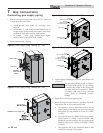
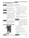
1. Remove the top access panel and refer to FIG.’s 7-1 thru 7-4
to pipe gas to the water heater.
a. Install ground joint union for servicing, when
required.
b. On Models 151 - 400 install a manual shutoff valve in
the gas supply piping outside water heater jacket when
required by local codes or utility requirements.
c. In Canada – When using manual main shutoff
valves, it must be identified by the installer.
2. Install sediment trap / drip leg.
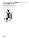
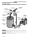
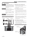
GAS SUPPLY
UNION
DRIP LEG
MANUAL
SHUT OFF
VALVE
Figure 7-1 Gas Supply Piping - Models 151 - 200
3. Support piping with hangers, not by the water heater or its
accessories.
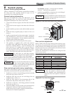
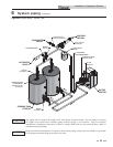
SEDIMENT TRAP / DRIP LEG
Figure 7-2 Gas Supply Piping - Models 286 - 400
4. Purge all air from the gas supply piping.
5. Before placing the water heater in operation, check the
water heater and its gas connection for leaks.
a. The appliance must be disconnected from the gas
supply piping system during any pressure testing of
that system at a test pressure in excess of 1/2 PSIG
(3.5 kPa).
b. The appliance must be isolated from the gas supply
piping system by closing a manual shutoff valve
during any pressure testing of the gas supply piping
system at test pressures equal to or less than 1/2 PSIG
(3.5 kPa).
c. The appliance and its gas connection must be leak
tested before placing it in operation.
The gas valve and blower will not support
the weight of the piping. Do not attempt
to support the weight of the piping with
the water heater or its accessories. Failure
to comply could result in severe personal
injury, death, or substantial property
damage.
ƽ WARNING
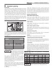
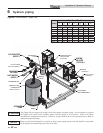
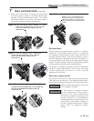
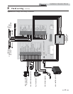
UNION
(FACTORY INSTALLED)
GAS SUPPLY
SEDIMENT TRAP/
DRIP LEG
MANUAL
SHUTOFF VALVE
(FACTORY SUPPLIED)
Figure 7-3 Gas Supply Piping - Model 501
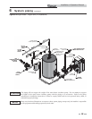
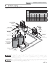
UNION
(FACTORY INSTALLED)
MANUAL
SHUTOFF VALVE
(FACTORY SUPPLIED)
GAS SUPPLY
SEDIMENT TRAP/
DRIP LEG
Figure 7-4 Gas Supply Piping - Models 601 - 801
44