


42 Room Air Conditioner
Installation
1. Check that all tubing and wiring have been properly
connected.
2. Check that the gas and liquid side service valves are
fully open.
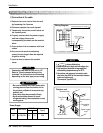
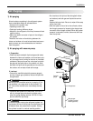
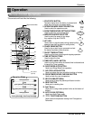
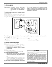
1. Prepare remote control
1. Remove the battery cover
by pulling it according to the
arrow direction.
2. Insert new batteries making
sure that the (+) and (–) of
battery are installed correctly.
3. Reattach the cover by
pushing it back into position.
NOTE:
• Use 2 AAA(1.5volt) batteries. Do not use recharge-
able batteries.
• Remove the batteries from the remote control if the
system is not going to be used for a long time.
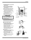
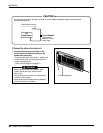
2. Settlement of outdoor unit
• Anchor the outdoor unit with a bolt and nut(ø10mm)
tightly and horizontally on a concrete or rigid mount.
• When installing on the wall, roof or rooftop, anchor the
mounting base securely with a nail or wire assuming
the influence of wind and earthquake.
• In the case when the vibration of the unit is conveyed
to the hose, secure the unit with an anti-vibration
bushing.
3. Evaluation of the performance
Operate unit for 15~20 minutes, then check the system
refrigerant charge:
1. Measure the pressure of the gas side service valve.
2. Measure the temperature of the intake and discharge
of air.
3. Ensure the difference between the intake tempera-
ture and the discharge is more than 8°C(46°F) (Cool-
ing) or (Heating).
4. For reference; the gas side pressure of optimum con-
dition is as below.(Cooling)
NOTE: If the actual pressure is higher than shown, the
system is most likely over-charged, and charge
should be removed. If the actual pressure are
lower than shown, the system is most likely
undercharged, and charge should be added.
The air conditioner is now ready for use.
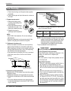
Bolt
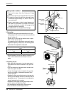
Tubing connection
Discharge air
Discharge
temperature
Intake temperature
R-410A 35°C (95°F) 8.5~9.5kg/cm
2
G(120~135 P.S.I.G)
Outside ambient
TEMP.
Refrigerant
The pressure of the gas side
service valve.
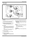
This is performed when the unit is to be relocated
or the refrigerant circuit is serviced.
Pump Down means collecting all refrigerant in the
outdoor unit without loss in refrigerant gas.
CAUTION:
Be sure to perform Pump Down procedure with the
unit cooling mode.
Pump Down Procedure
1. Connect a low-pressure gauge manifold hose to
the charge port on the gas side service valve.
2. Open the gas side service valve halfway and purge
the air from the manifold hose using the refrigerant
gas.
3. Close the liquid side service valve(all the way in).
4. Turn on the unit's operating switch and start the
cooling operation.
5. When the low-pressure gauge reading becomes 1
to 0.5kg/cm2 G(14.2 to 7.1 P.S.I.G.), fully close the
gas side valve stem and then quickly turn off the
unit. At that time, Pump Down has been completed
and all refrigerant gas will have been collected in
the outdoor unit.
PUMP DOWN
Test Running