


34 Room Air Conditioner
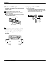
Installation
1
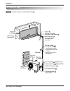
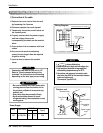
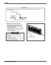
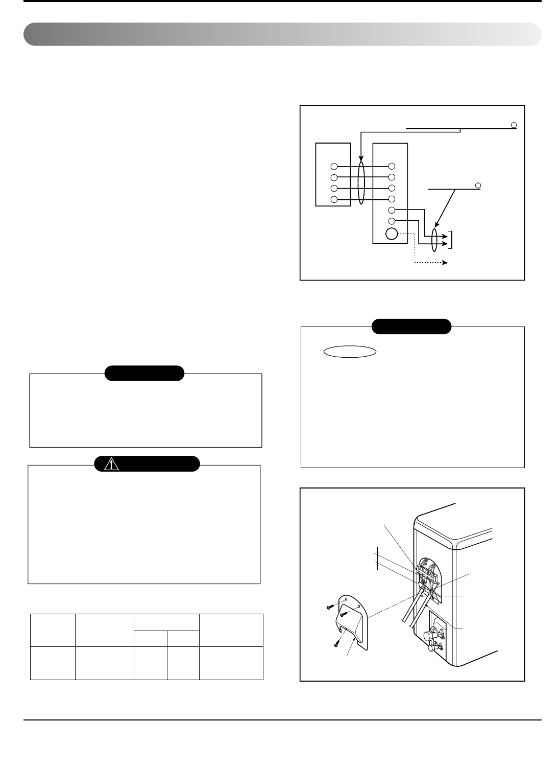
Indoor Unit Outdoor Unit
2
3
4
1
2
3
4
5
6
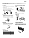
G
To
branch
circuit
Ground
Power supply
a
L1
*
L2
Connecting cable(Low voltage)
b
Terminal
(4P)
Terminal
(6P)
Outdoor unit
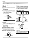
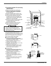
Wiring Diagram
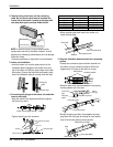
Terminal block
Over 5mm
(2")
Cover control
Conduit panel
Connecting
cable
Power supply
cord
*
L1 is neutral for 115V models.
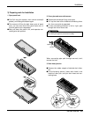
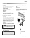
1) Connection of the cable
1. Remove the cover control from the unit
by loosening the 3 screws.
2. Dismount caps on the conduit panel.
3. Temporarily mount the conduit tubes on
the conduit panel.
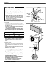
4. Properly connect both the power supply
and low voltage lines to the
corresponding terminals on the terminal
block.
5. Ground the unit in accordance with local
codes.
6. Be sure to size each wire allowing
several inches longer than the required
length for wiring.
7. Use lock nuts to secure the conduit
tubes.
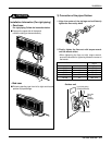
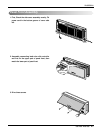
1. shows field wiring.
2. Separately wire the high and low voltage line.
3. Use heat-proof electrical wiring capable of
withstanding temperatures up to 167°F.
4. Use outdoor and waterproof connection cable
rated more than 300V for the connection between
indoor and outdoor unit.
(For example, Type SJO-WA)
• Be sure to comply with local codes while
running the wire from the indoor unit to
the outdoor unit(size of wire and wiring
method, etc).
• Every wire must be connected firmly.
• No wire should be allowed to touch
refrigerant tubing, the compressor or any
moving parts.
Connector trade size for this unit is 1/2".
Refer to "How to connect wiring to the
terminals" for instructions on connecting
depending on the wire type you are using.
WARNING
NOTE
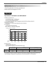
Power Supply
Model
Power source
18K 1ø, 208/230V 14 18 20A
AWG(MIN.)
Fuse or breaker
Capacity
NOTE
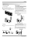
Connecting The Cable Between Indoor Unit and Outdoor Unit