


25
NOTE: DIAGRAMS & ILLUSTRATIONS ARE NOT TO SCALE.
COMPONENT INFORMATION
The following is a list of components and their functions.
Igniter
The Winslow™ PS40 stove comes equipped with an automatic igniter
for lighting the fuel when the stove is in the lighting mode. The igniter
superheats air that is pulled through the Burn-Pot by the combustion
blower to light the fuel. The igniter remains energized for the first seven
minutes of the lighting sequence.
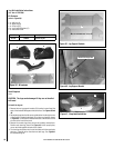
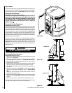
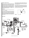
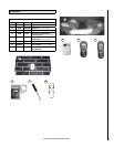
Vacuum Switch
The Winslow PS40 stove has a vacuum switch located behind the left
door, fastened to the pedestal base (see D in Figure 52). If a low pressure
is created in the firebox by a leak, opening the front door, a blocked flue,
or unsealed ash drawer, the vacuum switch will sense it and cause the
stove to go into a shutdown mode.
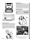
Auger and Auger Motor
The 1.25 RPM auger motor turns the auger, lifting pellets up the auger
tube. The pellets are then dropped down a tube and into the burn-pot.
The auger is controlled by the control board.
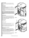
Over Temperature Snap Switch (Manual Reset)
(Opens at 225° F) This switch is installed on the convection blower (see F
in Figure 53) and shuts the stove down if it senses excessive temperatures.
This snap switch has a reset button on it and will not allow the stove to
start up until the reset button has been pushed.
Proof of Fire Snap Switch
(Closes at 140°F) This switch is installed on the combustion blower
(see E in Figure 52) and shuts the stove down if it senses no fire in the
Burn-Pot.
Convection Blower Snap Switch
(Closes at 120°F) This switch is installed on the right rear of the firebox
and turns the convection blower on when the stove gets up to temperature.
Hopper Lid Switch
It is located on the back right side of the hopper (on the outside of the
hopper). It detects whether the hopper lid is open and will turn off the
auger motor if the hopper lid is not properly closed. When opening the
hopper when refueling, do not allow the hopper lid to remain open too
long or the fire may extinguish. NEVER DISCONNECT OR BYPASS THIS
SWITCH FOR ANY REASON.
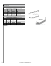
A
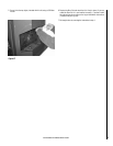
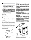
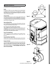
Flue Outlet
Air Intake
B
C
D
E
F
Figure 51
Figure 52
Figure 53