


12
NOTE: DIAGRAMS & ILLUSTRATIONS ARE NOT TO SCALE.
Mobile Home Installations
In addition to the standard installation instructions, the following instruc-
tions may be required by local, state or federal building codes.
• Installation should be in accordance with the Manufactured Home and
Safety Standard (HUD), CFR 3280, Part 24.
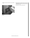
• The stove must be permanently bolted to the floor using 1/4" diameter
lag screws. The screws can be inserted through the holes in the
pedestal located behind the side doors. The lag screws must be an
adequate length to extend through the hearth pad and into the floor.
A minimum of two lag screws must be used.
• Connecting the Winslow™ PS40 stove to outside combustion air is
required in manufactured home installations and when required by
local building codes. An outside air inlet must be provided for com-
bustion and be unrestricted while unit is in use. Use a galvanized or
stainless steel pipe for the duct (the outside air inlet on the stove is 3”
diameter). The air intake on the exterior of the home should always be
located a minimum of 18” below the flue termination. The Inlet shall
remain free of obstruction while unit is in operation and constructed
in a manner so as to prevent material from dropping into the inlet or
into the area beneath the dwelling. The inlet shall also have a screen
with openings not larger than 1/4" to prevent rodents from entering.
• The stove must be permanently electrically grounded to the steel
chassis of the manufactured home using a 8 GA copper wire and a
serrated or star washer (to penetrate paint or protective coating to
ensure grounding). The location selected for ground attachment to the
stove must be dedicated for this purpose. Grounding must comply
with NFPA-70-latest edition standards, CSA C22.1-latest edition in
Canada, as well as any local codes.
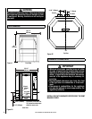
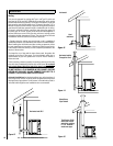
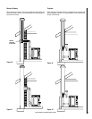
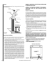
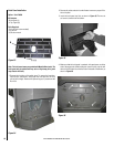
Vertical
If the length of pipe exceeds 15 feet, 4 inch pipe rather than 3 inch vent
pipe should be used.
WARNING: DO NOT INSTALL THIS STOVE IN A SLEEPING ROOM
IN A MANUFACTURED HOME.
CAUTION: THE STRUCTURAL INTEGRITY OF THE MANUFAC-
TURED HOME FLOOR, WALL AND CEILING/ROOF MUST BE
MAINTAINED.
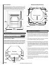
Outside Air Installations
Connecting the Winslow PS40 stove to outside combustion air is required
in manufactured home installations and when required by local building
codes. The stove’s air intake will accept 3” ID pipe to accommodate outside
air installations. The air intake on the exterior of the home should always
be located a minimum of 18” below the flue termination and must remain
free of obstruction. The inlet must also have a screen with openings not
larger than 1/4” to prevent rodents from entering.
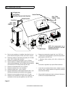
Thermostat installation
The Winslow PS40 stove can be operated manually or by thermostat. The
stove comes from the factory wired to operate manually - see control
board operation on Page 19. A low voltage thermostat can be installed
on the stove. To install the thermostat:
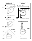
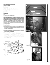
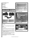
1) Unplug the stove from the electrical outlet. Open the right side door
and lift out the control board from its retaining brackets. Locate the
light green wiring block at the bottom back of the board (see Figure
21), loosen the two screws B at the back of the block and remove the
U shaped jumper wire A protruding from the block.
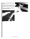
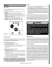
2) Insert a wire from the thermostat into one of the slots from which
the jumper wire was removed. Repeat this process for the other
thermostat wire.
Retain the jumper wire for future reinstallation. See Page 19 for thermostat
operation instructions.
IMPORTANT NOTE: Install the thermostat per the manufacturers
instructions, provided with the thermostat. Failure to follow
manufacturers instructions could result in a malfunction. Pay
special attention to the thermostat location requirements. If the
location requirements are not adhered to the appliance, erratic
operation or failure may occur.
Do not mount the thermostat where it may be affected by:
• Radiant heat from the stove, fireplaces, sun or other heat
sources.
• Drafts or dead spots behind doors or in corners.
• Hot or cold air from ducts.
Listed Pellet Pipe
Ceiling Firestop
Storm Collar
Roof Flashing
Rain Cap
Outside Air Pipe
Figure 20
Figure 21
Wiring Block
B
A
Rear View of Control Board
A = Jumper Wire
B = Screws
A B
Rear View of Control Board
Wiring Block