


Page 8
505067M 7/13/05
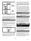
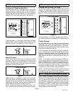
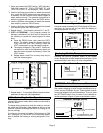
Smart Setback Recovery (via DIP switch #6)
Smart Setback Recovery (SSR) affects the way the ther-
mostat responds to program events. If SSR is disabled, the
thermostat will react to a program event at the time the
event occurs. However, if SSR is enabled, the thermostat
will react to a program event before the event occurs such
that the desired temperature is reached at the time of the
event, not after.
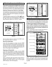
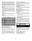
Autochangeover Deadband Selection (via DIP
switch #7)
Autochangeover deadband can be set to 4 or 6 degrees.
When autochangeover is enabled (via the AUTO button),
the thermostat will automatically change over from heating
to cooling and vice versa, to keep the room temperature in
between the heating and cooling setpoints. The deadband
is the minimum difference between the heating and cooling
setpoints.
Fan Control
AUTO or ON modes, gas or electric heat compatible via
DIP switches (also see Thermostat Output section).
I/O Relays
All thermostat relays are latching type to minimize power
consumption.
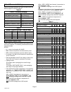
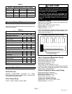
Table 5
51M38 Terminal Designations
Terminal Description
R 24VAC
Y1 First stage cooling
W1 First stage heating
G Fan control
L Service Indicator
C 24VAC common
T Outdoor temperature sensor connection 1
T Outdoor temperature sensor connection 2
Equipment Protection Timers
Minimum Compressor OFF time: 5 minutes
Minimum Compressor ON time: 4 minutes
Minimum Furnace ON time: 3 minutes
Minimum furnace cycle time (elapsed time between any
furnace activation and the next furnace activation): 6 min-
utes.
Minimum elapsed time between any compressor activa-
tion and the next compressor activation: 6 minutes.
NOTE − All protection timers (except the compressor OFF
timer) can be over−ridden if a heating or cooling demand is
initiated or terminated using the UP, DOWN, HEAT, or
COOL buttons.
Equipment Protection Override
Both the minimum compressor OFF timer and the mini-
mum equipment cycle timer can be over−ridden by press-
ing and holding either the HEAT or COOL button down for 4
seconds.
Over−Temperature Protection
Thermal-mechanical switch opens W1 at 93°F+/−6°F.
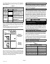
Filter Reminder
Settings of Off, 1, 3, 6 or 12 (months of fan run time) are
available. When programmed time has elapsed, a FILTER
indicator is displayed.
Maintenance Reminder
Settings of Off, 6 or 12 (months of chronological time) are
available. When programmed time has elapsed, a MAIN-
TENANCE indicator is displayed.
Service Reminder
The SERVICE indicator is displayed only under the follow-
ing conditions:
S if the thermostat Y1 terminal has been activated with
24VAC for at least 5 minutes, AND the L terminal is
shorted to the R terminal;
OR
S if the thermostat Y1 terminal has been activated with
24VAC for at least 5 minutes, AND the L terminal is
shorted to the C terminal.
Power Loss/Recovery
Thermostat memory is retained for a minimum of 24 hours
during a power loss (includes retention of clock setting,
program information, HOLD status, programmed temper-
ature setpoint, heat/cool and fan mode settings, filter re-
minder status, maintenance reminder status, and equip-
ment protection timers). After 24 hours of power loss,
programmed settings will be lost and replaced with default
settings.
IMPORTANT
Power must be applied for at least six consecutive
hours prior to a power loss in order for memory to
be retained for the specified time.
LCD Backlight
Activated for 30 seconds when any button is pressed.
NOTE − During an electrical storm or similar disturbance,
the backlight may activate for a few seconds. This is nor-
mal and will no longer occur after the electrical disturbance
has passed.
Thermostat Operating Conditions
35°F to 105°F, 5% to 90% RH
Thermostat Storage Conditions
−40°F to 185°F, 5% to 95% RH