


Page 8
505068M 07/05
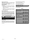
Technical Specifications
Thermostat Type
Electronic programmable thermostat for 2−Stage (gas or
electric) Heat/2-Stage Cool, non−heat pump, non−power
robbing applications.
Table 5
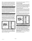
51M39 Terminal Designations
Terminal Description
R 24VAC
Y1 First-stage cooling
W1 First-stage heating
Y2 Second-stage cooling
W2 Second-stage heating
G Fan control
L Service Indicator
C 24VAC common
T Outdoor temperature sensor connection 1
T Outdoor temperature sensor connection 2
Power Supply Range
18VAC − 30VAC (24VAC nominal), 60Hz
CAUTION
24VAC is present on the terminals of the thermostat
bracket. If removing the thermostat from the wall,
use caution and avoid touching any of the connec-
tor terminals on the wall bracket.
Also, when working with the thermostat dip
switches, use a non−conductive tool and take cau-
tion to avoid making any contact with the circuit
board, its imprinted circuitry and its connector
prongs.
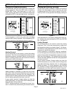
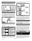
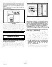
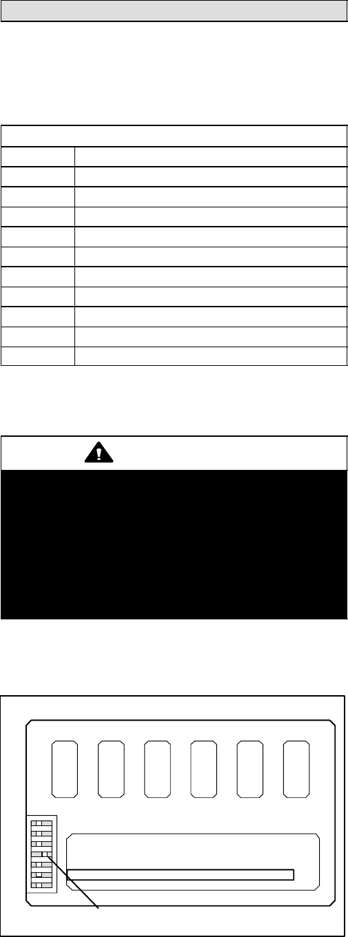
Temperature Display
Display Scale: Fahrenheit or Celsius user selectable (via
DIP switch; see figure 18)
F/C (Fahrenheit/Celsius) switch
shown in Celsius position
Figure 18
Changing Fahrenheit/Celsius Setting
1
2
3
4
5
6
7
PLUG IN (Use Care To Avoid Bending Prongs.)
Display range: 35°F (2°C) to 99°F (37°C)
Display resolution: 1°F (1°C)
Display Accuracy: +/−1°F
If the Fahrenheit/Celsius display must be changed, use a
plastic, non−conductive tool to push the dip switch to the
right position (see figure 18).
Indoor Temperature Measurement Range
Measurement Scale: Fahrenheit
Measurement Range: 35°F to 99°F
Measurement Resolution: 0.5°F
Measurement Accuracy: +/−1°F
Field Offset: via DIP switches to +/−3°F
Sampling Method: temperature measurements sampled
every 15 seconds. Displayed temperature is the average
of the last four measurements.
Outdoor Temperature Measurement Range
Measurement Scale: Fahrenheit
Measurement Range: −22°F to 122°F
Measurement Resolution: 1°F
Measurement Accuracy: +/−2°F
Temperature Setpoint Range
Setting range: 50°F (10°C) to 90°F (32°C)
Setting resolution: 1°F (1°C)
Smart Setback Recovery (via DIP switch #6)
Smart Setback Recovery (SSR) affects the way the ther-
mostat responds to program events. If SSR is disabled, the
thermostat will react to a program event at the time the
event occurs. However, if SSR is enabled, the thermostat
will react to a program event before the event occurs such
that the desired temperature is reached at the time of the
event, not after.
Autochangeover Deadband Selection (via DIP
switch #7)
Autochangeover deadband can be set to 4 or 6 degrees.
When autochangeover is enabled (via the AUTO button),
the thermostat will automatically change over from heating
to cooling and vice versa, to keep the room temperature in
between the heating and cooling setpoints. The deadband
is the minimum difference between the heating and cooling
setpoints.
Fan Control
AUTO or ON modes, gas or electric heat compatible via
DIP switches (also see Thermostat Output section).
I/O Relays
All thermostat relays are latching type to minimize power
consumption.
Equipment Protection Timers
Minimum Compressor OFF time: 5 minutes
Minimum Compressor ON time: 4 minutes
Minimum Furnace ON time: 3 minutes
Minimum furnace cycle time (elapsed time between any
furnace activation and the next furnace activation): 6 min-
utes.
Minimum elapsed time between any compressor activa-
tion and the next compressor activation: 6 minutes.