


Page 8
506586−01 10/10
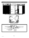
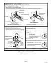
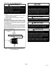
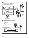
LEG DETAIL
BASE
2" (50.8MM) SCH 40
FEMALE THREADED
ADAPTER
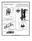
Concrete slab Ċ use two plastic anchors (hole
drill 1/4")
Wood or plastic slab Ċ no plastic anchor (hole
drill 1/8")
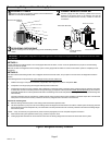
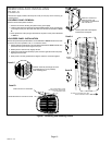
COIL
BASE PAN
CORNER POST
STABILIZING BRACKET (18 GAUGE
METAL Ċ 2" WIDTH; HEIGHT AS
REQUIRED)
Ċ Slab Side Mounting
#10 1/2" LONG SELF−DRILLING
SHEET METAL SCREWS
#10 1−1/4" LONG HEX HD SCREW
AND FLAT WASHER
MINIMUM ONE
PER SIDE
Stabilizing bracket (18 gauge metal Ċ 2" (50.8mm) width; height as required); bend to form
right angle as exampled below.
FOR EXTRA
STABILITY
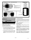
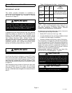
Ċ Deck Top Mounting
Ċ Elevated Slab Mounting
using Feet Extenders
STABILIZING UNIT ON UNEVEN SURFACES
Install unit level or, if on a slope, maintain slope tolerance of two (2)
degrees (or two inches per five feet [50 mm per 1.5 m]) away from
building structure.
MOUNTING
SLAB
BUILDING
STRUCTURE
GROUND LEVEL
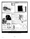
Ċ Outside Unit Placement
Ċ Slab Mounting at Ground Level
SAME FASTENERS AS
SLAB SIDE MOUNTING.
IMPORTANT Ċ To help stabilize an outdoor unit, some installations may require strapping the unit to the pad using brackets and anchors
commonly available in the marketplace.
DETAIL A
DETAIL B
DETAIL C
DETAIL D
2" (50.8MM) SCH 40
MALE THREADED
ADAPTER
Use additional 2" SCH 40 male threaded adapters
which can be threaded into the female threaded
adapters to make additional adjustments to the level of
the unit.
TWO 90° ELBOWS INSTALLED IN LINE SET WILL
REDUCE LINE SET VIBRATION.
Install unit away from windows.
One bracket per side (minimum). For extra stability, two brackets per side, two inches
(51mm) from each corner.
DETAIL E
Figure 5. Placement, Slab Mounting and Stabilizing Unit