


Page 25
XP17 SERIES
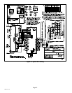
Field Control Wiring
Y1
O
R
W1
G
D
R
Y1
L
C
C
B
Y2
Y2
i−
W
O
i+
DS
L
T
T
W2
H
W3
H
O
C
L
Y2
DS
DH
G
R
Y1
W2
W1
1
2
5
6
Air Hander Control
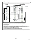
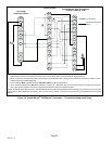
ComfortSense[ 7000 Thermostats
Catalog # Y0349 or Y2081
One−Stage
Heat Pump Control
On−board link
Low voltage thermostat
wiring
Flat metal jumper
4
3
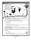
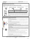
1. Thermostat T terminals are used for outdoor sensor input. Use for thermostat’s outdoor temperature display (optional).
2. R to L connection is required for this model when using the ComfortSense
®
7000 − catalog number Y0349 only. Resistor Kit (catalog number 47W97)
required and ordered separately.
3. Air handler control ships from factory with metal jumpers installed across W1, W2 and W3. For one−stage electric heat, do not remove factory
installed metal jumpers.
4. Air handler control ships from factory with metal jumpers installed across W1, W2 and W3. For two−stage electric heat, remove factory installed metal
jumper between W1 to W2. Then connect thermostat wire between the air handler control’s W2 and the thermostat’s W2 terminal.
5. Cut on−board link (clippable wire) from R−O HEAT PUMP for heat pump applications.
6. Cut on−board link (clippable wire) DS−R for Humiditrol
®
or Harmony IIIt applications. This will slow the indoor blower motor to the lowest speed
setting. See air handler installation instruction or engineering handbook for lowest fan speed information.
Figure 17. ComfortSense® 7000 Series Thermostat Ċ Air Hander/One−Stage Heat Pump