


Page 10
506586−01 10/10
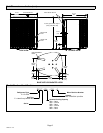
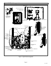
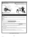
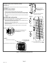
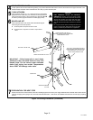
REMOVE 4 SCREWS TO
REMOVE PANEL FOR
ACCESSING COMPRESSOR
AND CONTROLS.
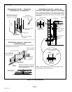
Position panel with holes aligned;
install screws and tighten.
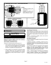
Detail A
Detail B
ROTATE IN THIS DIRECTION; THEN
DOWN TO REMOVE PANEL
SCREW
HOLES
LIP
Panel shown slightly rotated to allow top tab to exit (or enter) top slot for removing (or
installing) panel.
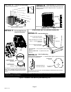
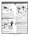
Maintain minimum panel angle (as close
to parallel with the unit as possible)
while installing panel.
PREFERRED ANGLE FOR INSTALLATION
Detail D
ANGLE MAY BE TOO EXTREME
HOLD DOOR FIRMLY ALONG
THE HINGED SIDE TO MAINTAIN
FULLY−ENGAGED TABS
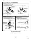
LOUVERED PANEL REMOVAL
Remove the louvered panels as follows:
1. Remove two screws, allowing the panel to swing open slightly.
2. Hold the panel firmly throughout this procedure Rotate bottom corner of panel away
from hinged corner post until lower three tabs clear the slots as illustrated in detail
B.
3. Move panel down until lip of upper tab clears the top slot in corner post as illustrated
in detail A.
LOUVERED PANEL INSTALLATION
Position the panel almost parallel with the unit as illustrated in detail D with the screw side
as close to the unit as possible. Then, in a continuous motion:
1. Slightly rotate and guide the lip of top tab inward as illustrated in detail A and C; then
upward into the top slot of the hinge corner post.
2. Rotate panel to vertical to fully engage all tabs.
3. Holding the panel’s hinged side firmly in place, close the right−hand side of the panel,
aligning the screw holes.
4. When panel is correctly positioned and aligned, insert the screws and tighten.
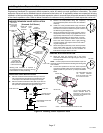
REMOVING AND INSTALLING
PANELS
WARNING
Detail C
Figure 7. Removing and Installing Panels