


Page 11
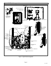
XP17 SERIES
New or Replacement Line Set
REFRIGERANT LINE SET
This section provides information on installation or
replacement of existing line set. If new or replacement line
set is not being installed then proceed to Brazing
Connections on page 13.
IMPORTANT
Lennox highly recommends changing line set when
converting the existing system from HCFC−22 to
HFC−410A. If that is not possible and the line set is the
proper size as reference in Table 2, use the procedure
outlined under Flushing the System on page 13.
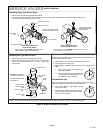
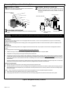
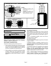
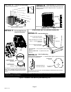
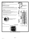
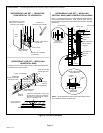
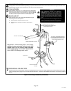
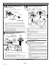
If refrigerant lines are routed through a wall, then seal and
isolate the opening so vibration is not transmitted to the
building. Pay close attention to line set isolation during
installation of any HVAC system. When properly isolated
from building structures (walls, ceilings. floors), the
refrigerant lines will not create unnecessary vibration and
subsequent sounds. See figure 8 for recommended
installation practices. Also, consider the following when
placing and installing a high−efficiency outdoor unit.
IMPORTANT
Refrigerant lines must not contact structure.
Liquid lines that meter the refrigerant, such as RFC1 liquid
lines, must not be used in this application. Existing line set
of proper size as listed in table 2 may be reused. If system
was previously charged with HCFC−22 refrigerant, then
existing line set must be flushed (see Flushing the System
on page 16).
Field refrigerant piping consists of liquid and vapor lines
from the outdoor unit to the indoor unit coil (braze
connections). Use Lennox L15 (sweat, non−flare) series
line set, or field−fabricated refrigerant line sizes as listed in
table 2.
Table 2. Refrigerant Line Set Ċ Inches (mm)
Model
Liquid
Line
Vapor
Line
L15
Line Sets
Feet (Meters)
−024 and
−030
3/8" (10) 3/4" (19)
L15 line set sizes are depen-
dent on unit match up. See
XP17 Engineering Handbook to
determine correct line set sizes.
−036, −042
and −048
3/8" (10) 7/8" (22)
−060 3/8" (10)
1−1/8"
(29)
Field Fabricated
NOTE Ċ Some applications may required a field provided 7/8" to
1−1/8" adapter
NOTE Ċ When installing refrigerant lines longer than 50
feet, see the Lennox Refrigerant Piping Design and
Fabrication Guidelines, or contact Lennox Technical
Support Product Applications for assistance. :
To obtain the correct information from Lennox, be sure to
communicate the following information:
S Model (XP17) and size of unit (e.g. −036).
S Line set diameters for the unit being installed as listed
in table 2 and total length of installation.
S Number of elbows vertical rise or drop in the piping.
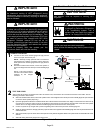
The compressor is charged with sufficient Polyol ester oil
for line set lengths up to 50 feet. Recommend adding oil to
system based on the amount of refrigerant charge in the
system. No need to add oil in system with 20 pounds of
refrigerant or less. For systems over 20 pounds − add one
ounce of every five pounds of refrigerant.
Recommended topping−off POE oils are Mobil EAL
ARCTIC 22 CC or ICI EMKARATEt RL32CF.
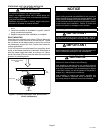
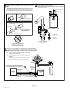
WARNING
Polyol Ester (POE) oils used with HFC−410A
refrigerant absorb moisture very quickly. It is very
important that the refrigerant system be kept closed
as much as possible. DO NOT remove line set caps
or service valve stub caps until you are ready to make
connections.
IMPORTANT
Mineral oils are not compatible with HFC−410A. If oil
must be added, it must be a Polyol ester oil.