


Page 4
506586−01 10/10
WARNING
Improper installation, adjustment, alteration, service or
maintenance can cause personal injury, loss of life, or
damage to property.
Installation and service must be performed by a licensed
professional installer (or equivalent) or a service agency.
CAUTION
Physical contact with metal edges and corners while
applying excessive force or rapid motion can result in
personal injury. Be aware of, and use caution when
working near these areas during installation or while
servicing this equipment.
IMPORTANT
The Clean Air Act of 1990 bans the intentional venting of
refrigerant (CFCs, HCFCs AND HFCs) as of July 1,
1992. Approved methods of recovery, recycling or
reclaiming must be followed. Fines and/or incarceration
may be levied for noncompliance.
WARNING
Electric Shock Hazard. Can cause injury
or death. Unit must be grounded in
accordance with national and local
codes.
Line voltage is present at all components
when unit is not in operation on units with
single-pole contactors. Disconnect all
remote electric power supplies before
opening access panel. Unit may have
multiple power supplies.
IMPORTANT
This model is designed for use in check expansion valve
systems only. An indoor expansion valve approved for
use with HFC−410A refrigerant must be ordered
separately, and installed prior to operating the system.
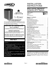
Shipping and Packing List
Check unit for shipping damage. Consult last carrier
immediately if damage is found.
1 Ċ Assembled outdoor unit.
1 Ċ Bag assembly which includes the following:
1 Ċ Bushing (for low voltage wiring)
2 Ċ Isolation grommets for liquid and suction lines
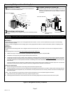
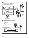
Using Manifold Gauge Set
When checking the system charge, only use a manifold
gauge set that features low−loss anti−blow back fittings.
IMPORTANT
To prevent stripping of the various caps used, the
appropriately sized wrench should be used and fitted
snugly over the cap before tightening.
Manifold gauge set used with HFC−410A refrigerant
systems must be capable of handling higher system
operating pressures. The gauges should be rated for use
with pressures of 0 − 800 psig on the high side and a low
side of 30" vacuum to 250 psig with dampened speed to
500 psi. Gauge hoses must be rated for use at or up to 800
psig of pressure with a 4000 psig burst rating.
Table 1. Torque Requirements
Parts Recommended Torque
Service valve cap 8 ft.− lb. 11 NM
Sheet metal screws 16 in.− lb. 2 NM
Machine screws #10 28 in.− lb. 3 NM
Compressor bolts 90 in.− lb. 10 NM
Gauge port seal cap 8 ft.− lb. 11 NM
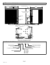
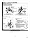
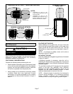
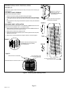
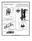
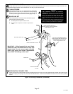
Operating Service Valves
The liquid and vapor line service valves are used for
removing refrigerant, flushing, leak testing, evacuating,
verifying charge and charging.
Each valve is equipped with a service port which has a
factory−installed valve stem. Figure 2 provides information
on how to access and operating both angle and ball service
valves.
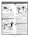
IMPORTANT
Only use Allen wrenches of sufficient hardness (50Rc −
Rockwell Harness Scale minimum). Fully insert the
wrench into the valve stem recess.
Service valve stems are factory−torqued (from 9 ft−lbs for
small valves, to 25 ft−lbs for large valves) to prevent
refrigerant loss during shipping and handling. Using an
Allen wrench rated at less than 50Rc risks rounding or
breaking off the wrench, or stripping the valve stem
recess.
See the Lennox Service and Application Notes #C−08−1
for further details and information.