


Page 43
XC17 SERIES
LED CODES AND SEQUENCE OF OPERATIONS
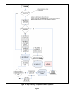
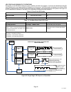
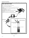
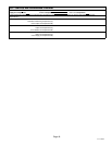
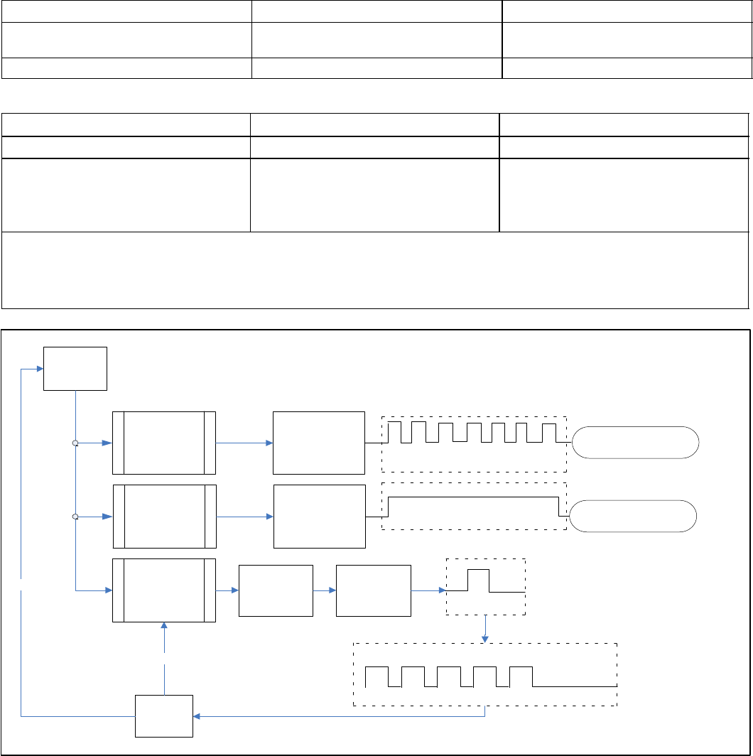
During start up, the LED will first display any error conditions (see table 12) if present. If no errors are detected then the LED
code indicating one or two stage operation will display then a long pause. The RPM indicator is displayed next. After the RPM
indicator is displayed there is a short pause and the sequence repeats if a thermostat demand is still present. See Figure 22
for LED sequence of operations. See table 13 for description of flash and pause durations.
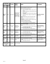
Table 12. Error/Fault LED Codes
Unit Status Motor Control LED Possible Cause
Mismatched RPM Fast Flash with no pause
Internal feedback, PWM does not match tar-
get.
CRC Failure Constant ON. Microcontroller CRC failure.
Table 13. Fan Motor Board Unit LED Codes
Unit Status Unit Status Motor Control LED
One Stage Operation Low Stage Ċ ECM1/Y1 ONLY One slow flash, then short pause.
RPM Indicator
NOTE Ċ There is a long pause between stage
operation and RPM indicator. See Tables 1 and 2
for LED RPM indicator.
RPM Indicator
Appropriate number of flashes (See Tables
11 and 2).
Flash Flash = Three flashes per second.
Slow Flash = One flash per second.
Short Pause = Two seconds of OFF time.
Long Pause = Five seconds of OFF time.
DEMAND
BEGINS
MISMATCHED
RPM
DEFAULT FAN
MOTOR SPEED
USED
LED CONTINUOUS FAST
FLASH
REPLACE FAN MOTOR
CONTROL BOARD
CRC FAILURE
DEFAULT FAN
MOTOR SPEED
USED
LED CONSTANT ON
REPLACE FAN MOTOR
CONTROL BOARD
SINGLE STAGE
OR EDA
OPERATION
FAN MOTOR PWM CONTROL (ONE STAGE AND
SINGLE FAN SPEED)
ECM1/Y1
ONLY OR
ECM2/Y2
ONLY
STAGE LED INDICATOR: ONE
SLOW FLASH AND ONE
SHORT PAUSE FOR SINGLE
STAGE OR EDA OPERATION
LED RPM INDICATOR:
EXAMPLE: (2−TON
UNIT) – 5 SLOW
FLASHES AND ONE
LONG PAUSE
DEMAND
ENDED
NO
YES
FAN MOTOR
RPM SET PER
JUMPER
SETTINGS
Figure 22. Single Stage LED Sequence of Operation