


Page 17
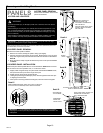
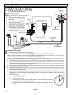
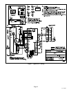
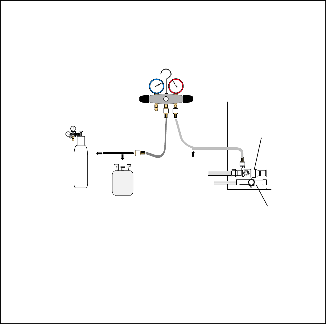
XC17 SERIES
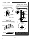
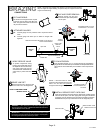
TO VAPOR
SERVICE VALVE
HFC−410A
MANIFOLD GAUGE SET
OUTDOOR UNIT
HIGHLOW
NITROGEN
NOTE Ċ Normally, the high pressure hose is connected to the liquid line port. How-
ever, connecting it to the vapor port better protects the manifold gauge set from high
pressure damage.
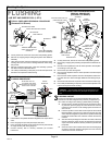
A With both manifold valves closed, connect the cylinder of HFC−410A refrigerant to the center port of the manifold gauge set. Open
the valve on the HFC−410A cylinder (vapor only).
B Open the high pressure side of the manifold to allow HFC−410A into the line set and indoor unit. Weigh in a trace amount of
HFC−410A. [A trace amount is a maximum of two ounces (57 g) refrigerant or three pounds (31 kPa) pressure]. Close the valve on
the HFC−410A cylinder and the valve on the high pressure side of the manifold gauge set. Disconnect the HFC−410A cylinder.
C Connect a cylinder of dry nitrogen with a pressure regulating valve to the center port of the manifold gauge set.
D Adjust dry nitrogen pressure to 150 psig (1034 kPa). Open the valve on the high side of the manifold gauge set in order to pressurize the
line set and the indoor unit.
E After a few minutes, open one of the service valve ports and verify that the refrigerant added to the system earlier is measurable
with a leak detector.
F After leak testing disconnect gauges from service ports.
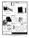
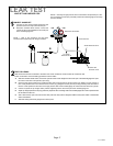
LINE SET AND INDOOR COIL
After the line set has been connected to the indoor unit and air conditioner, check the line set connections and
indoor unit for leaks. Use the following procedure to test for leaks:
LEAK TEST
A Connect an HFC−410A manifold gauge set high
pressure hose to the vapor valve service port.
B With both manifold valves closed, connect the
cylinder of HFC−410A refrigerant to the center port
of the manifold gauge set.
1
CONNECT GAUGE SET
2
TEST FOR LEAKS
A
B
NOTE Ċ Later in the procedure, the HFC−410A
container will be replaced by the nitrogen container.
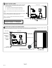
LIQUID LINE
SERVICE VALVE
VAPOR SERVICE VALVE