


Page 11
XC17 SERIES
New or Replacement Line Set
REFRIGERANT LINE SET
This section provides information on installation or
replacement of existing line set. If new or replacement line
set is not being installed then proceed to Brazing
Connections on page 13.
IMPORTANT
Lennox highly recommends changing line set when
converting the existing system from HCFC−22 to
HFC−410A. If that is not possible and the line set is the
proper size as reference in Table 2, use the procedure
outlined under Flushing the System on page 13.
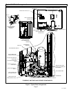
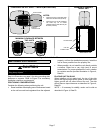
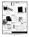
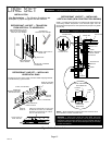
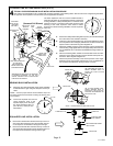
If refrigerant lines are routed through a wall, then seal and
isolate the opening so vibration is not transmitted to the
building. Pay close attention to line set isolation during
installation of any HVAC system. When properly isolated
from building structures (walls, ceilings. floors), the
refrigerant lines will not create unnecessary vibration and
subsequent sounds. See Figure 5 for recommended
installation practices. Also, consider the following when
placing and installing a high−efficiency outdoor unit.
Liquid lines that meter the refrigerant, such as RFC1 liquid
lines, must not be used in this application. Existing line set
of proper size as listed in Table 2 may be reused. If system
was previously charged with HCFC−22 refrigerant, then
existing line set must be flushed (see Flushing the System
on page 14).
Field refrigerant piping consists of liquid and vapor lines
from the outdoor unit to the indoor unit coil (braze
connections). Use Lennox L15 (sweat, non−flare) series
line set, or field−fabricated refrigerant line sizes as listed in
Table 2.
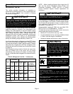
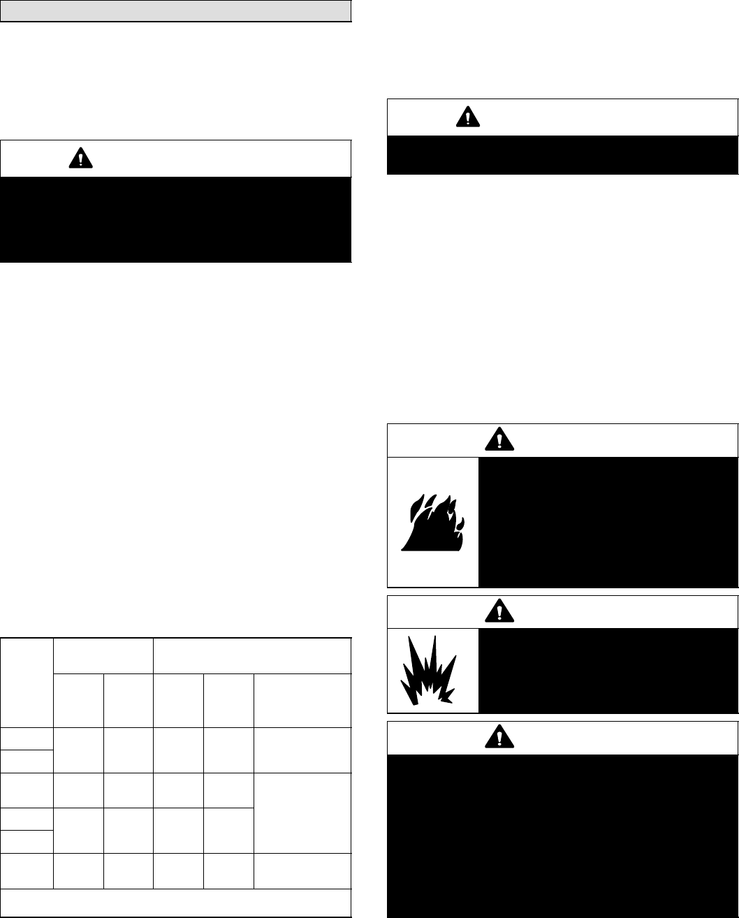
Table 2. Refrigerant Line Set Ċ Inches (mm)
Model
Size
Field
Connections
Recommended Line Set
Liquid
Line
Vapor
Line
Liquid
Line
Vapor
Line
L15
Line Sets
Feet (Meters)
−024
3/8
(10)
3/4
(19)
3/8
(10)
3/4
(19)
L15−41
15 − 50’ (5 − 15)
−030
−036
3/8
(10)
7/8
(22)
3/8
(10)
7/8
(22)
L15−65
15 − 50’ (5 − 15)
−042
3/8
(10)
7/8
(22)
3/8
(10)
7/8
(22)
−048
−060
3/8
(10)
1−1/8.
(29)
3/8
(10)
1−1/8
(29)
Field Fabricated
NOTE Ċ Some applications may required a field provided 7/8" to
1−1/8" adapter
NOTE Ċ When installing refrigerant lines longer than 50
feet, see the Lennox Refrigerant Piping Design and
Fabrication Guidelines, CORP. 9351−L9, or contact
Lennox Technical Support Product Applications for
assistance.
IMPORTANT
Mineral oils are not compatible with HFC−410A. If oil
must be added, it must be a Polyol ester oil.
The compressor is charged with sufficient Polyol ester oil
for line set lengths up to 50 feet. If line set lengths longer
than 50 feet will be required, all one (1) ounce of oil for
every additional 10 feet of line set. Do not add any more
than seven (7) ounces of oil.
Recommended topping−off POE oils are Mobil EAL
ARCTIC 22 CC or ICI EMKARATEt RL32CF.
To obtain the correct information from Lennox, be sure to
communicate the following information:
S Model (XC17) and size of unit (e.g. −036).
S Line set diameters for the unit being installed as listed
in Table 2 and total length of installation.
S Number of elbows vertical rise or drop in the piping.
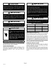
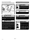
WARNING
Danger of fire. Bleeding the refrigerant
charge from only the high side may result
in the low side shell and suction tubing
being pressurized. Application of a
brazing torch while pressurized may
result in ignition of the refrigerant and oil
mixture − check the high and low
pressures before unbrazing.
WARNING
When using a high pressure gas such as
dry nitrogen to pressurize a refrigeration
or air conditioning system, use a
regulator that can control the pressure
down to 1 or 2 psig (6.9 to 13.8 kPa).
CAUTION
Brazing alloys and flux contain materials which are
hazardous to your health.
Avoid breathing vapors or fumes from brazing
operations. Perform operations only in well ventilated
areas.
Wear gloves and protective goggles or face shield to
protect against burns.
Wash hands with soap and water after handling brazing
alloys and flux.