


Page 42
506510−01
Maintenance
WARNING
Electric shock hazard. Can cause injury
or death. Before attempting to perform
any service or maintenance, turn the
electrical power to unit OFF at disconnect
switch(es). Unit may have multiple power
supplies.
WARNING
Improper installation, adjustment, alteration, service or
maintenance can cause personal injury, loss of life, or
damage to property.
Installation and service must be performed by a licensed
professional installer (or equivalent) or a service agency.
DEALER
Verifying Fan Motor Operation
FAN MOTOR CONTROL AND START UP
This motor control is used in controlling motors which
employ a Pulse Width Modulation (PWM) controller. A
PWM signal will run the fan motor at a revolutions per
minute (RPM) that corresponds to a specific PWM signal.
VERIFYING JUMPER SETTINGS (J2)
The unit is shipped from the factory with the default motor
RPM setting required for the specific model size. Use table
11 for one−stage to verify that the jumpers are set correctly
for the specific size unit.
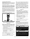
VERIFYING LED STATUS CODES
During start up, the fan motor control LED will
display any error conditions. If error conditions
exist then no other codes will display. If no error
conditions are present, then the stage status and
and RPM indicator are displayed. Fan motor speeds
are not adjustable for a single stage outdoor unit (see
table 11).
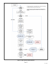
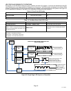
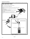
VERIFYING CORRECT DC OUTPUT VOLTAGE (J2)
The following three methods can be used to determine
whether the fan motor is operating at the correct RPMs
based on unit size.
1. Use the information provided in tables 11 to verify that
all four jumper terminals are set correctly for the
specific size unit.
2. Verify LED RPM indicator is displaying the correct
flash sequence for the applicable size unit (see Table
11).
3. Test DC voltage output on the Motor Control’s J2
terminals (see Figure 23) while under full load and
verify the voltage read to the voltage listed in Table 11
for the applicable size unit.
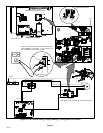
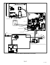
4. If no voltage is detected at the J2 terminals, verify
there is a Y1 demand at the thermostat and 24V
present at the Fan Control’s EXT PWR/R terminal
during that Y1 demand (see Figure 24).
5. If 24V is present at the Fan Control EXT PWR/R
terminal during a Y1 thermostat demand, and no
voltage is present at the J2 terminals, then Fan Control
should be replaced.
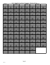
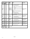
Table 11. One Stage Ċ Motor Control RPM Jumper Settings, LED RPM Indicator and P2 DC Voltage Outputs
Model LED Code*
CFM Profile Pin Select
ECM1/Y1
(One Stage and EDA Operation)
4 3 2 1 RPM (J2) DC Volt
XP/XC17−048, −060 9 OFF OFF OFF ON 675 21.6
XP/XC17−036, −042 8 OFF OFF ON ON 600 19.2
XP/XC17−030 6 OFF ON ON OFF 450 14.3
XP/XC17−024 5 OFF ON ON ON 400 12.7
* LED Code indicates Fan Control LED flash sequence. For example, LED Code 9 indicates 9 slow flashes and pause.