


26
NOTE: DIAGRAMS AND ILLUSTRATIONS ARE NOT TO SCALE
CAUTION: Wear gloves and safety glasses for protection while
doing required maintenance.
Verify proper operation after servicing.
S'assurer que l'appareil fonctionne adéquatement une fois
l'entretien terminé.
Maintenance Checklist
The following should only be performed by a qualified service techni-
cian.
1. Annual inspection should be made and the following checks
performed:
p When unit is cool, remove glass and inspect burner for dirt, soot,
and lint accumulations, and remove if necessary. If excessive soot
accumulation is present on burner, have a qualified service technician
adjust the burner for proper combustion.
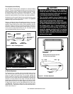
p Clean inside of glass with gas fireplace glass cleaner. NEVER attempt
to remove or clean the glass when the unit is hot.
p Check the hot air outlet vents for lint or other accumulations. Never
block or restrict vent openings, obstruct flow of ventilation air, or use
vents other than Lennox Hearth Products products.
p Check that the chimney and its outlet are open and free of soot, block-
age, or debris.
p Check gaskets once a year. Gaskets must be tight. Replace if neces-
sary.
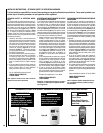
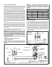
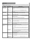
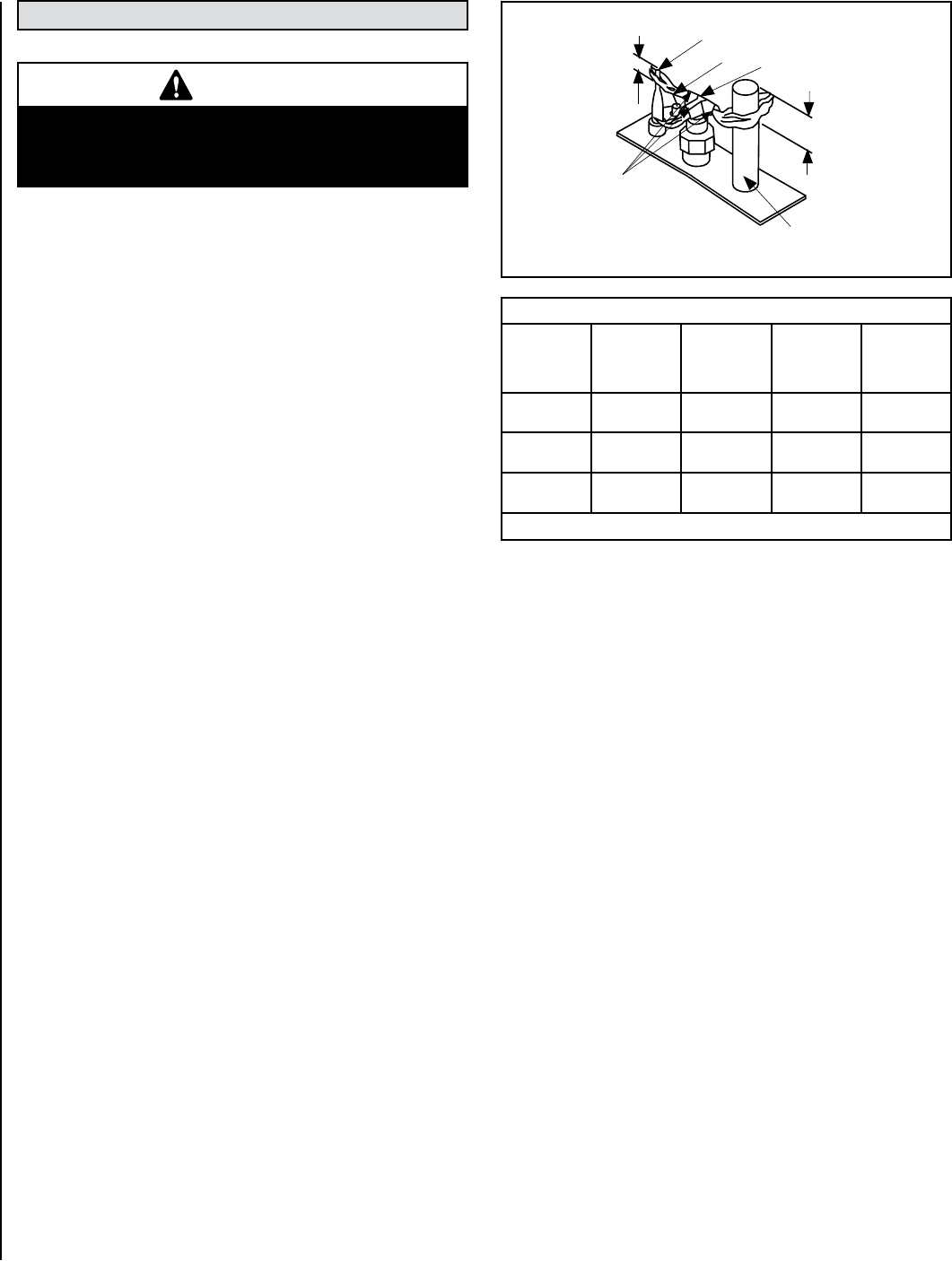
p Inspect the pilot system for proper flame (see Figure 39). NEVER
ADJUST THE PILOT until after the gas pressure has been checked
and the supply lines have been completely bled (this may take an hour
or more when bleeding through the pilot). All pilots are checked and
burned at the factory prior to shipment. The pilot adjustment screw
is located below the ON/OFF/PILOT control knob. Remove the pilot
adjusting cover with a flat-bladed screwdriver to access the pilot
adjusting screw. Adjust the pilot screw to properly size the flames.
The flames should directly contact the thermopile and extend across
the main burner ports. Be careful not to back the screw out of its
threads. Replace the cover and check for gas leaks using a gas leak
test solution.
p Check that the area around the insert is kept clear and is free of
combustible materials, gasoline, and other flammable vapors and
liquids.
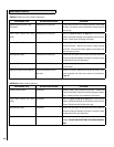
p Check the millivolt system as per Table 13.
2. The viewing glass should be cleaned periodically (see Glass
Maintenance).
MAINTENANCE AND SERVICING
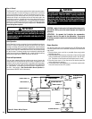
Check
Test
To
Test
Connect
Meter
Leads to
Terminals
Thermostat
Connects
Meter Read-
ing
Should Be
A Complete
System
2 & 3 Closed 100 MV
or More
B Thermopile
Output
1 & 2 Open Greater Than
325 MV
C System
Resistance
2 & 3 Closed 2.5 Ohms
Table 13
Thermocouple
Thermopile
Pilot
Nozzels
1/8" Min.
(3 mm)
Igniter Rod
Hood
3/8" Min.
(9 mm)
Figure 39 - Proper Pilot Flame Appearance
WARNING
Turn off gas and electrical power to the fireplace
and allow it to cool before cleaning or servicing
the appliance.
Blower Removal
CAUTION: Label all wires prior to disconnection when servicing
controls. Wiring errors can cause improper and dangerous opera-
tion.
.25
IMPORTANT: Verify proper operation after servicing (see the blower
wiring diagram In Figure 36 on Page 24).
1. Unplug the power supply cord from the electrical outlet prior to remov-
ing the blower. The blower can be accessed through the back wall of
the firebox.
2. Remove the insert face, glass door, log set, and brick panels. All of
these items are fragile so handle them with care.
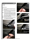
3. Next, remove the nine allen head screws around the outside of the
panel fastened to the back wall of the firebox.
4. Rotate the top of this panel toward the front, remove the two wires
connected to the blower, and then lift the panel with the blower attached
out of the firebox.
To reinstall the blower, repeat these steps in the reverse order.