


2
CONGRATULATIONS!
When you purchased your new gas fireplace insert, you joined
the ranks of thousands of individuals whose answer to their home
heating needs reflects their concern for aesthetics, efficiency
and our environment. We extend our continued support to help
you achieve the maximum benefit and enjoyment available from
your new gas fireplace insert.
Thank you for selecting a Lennox Hearth Products gas fireplace
insert as the answer to your home heating needs.
TABLE OF CONTENTS
Packaging List ...................................................................Page 2
Using this Manual .............................................................Page 2
Introduction ......................................................................Page 2
Safety and Warning Information .......................................Page 3
General Information ..........................................................Page 5
Smoke Detectors ...............................................................Page 6
Codes and Approvals ........................................................Page 6
New York City MEA Approval ............................................Page 7
Requirements for the
Commonwealth of Massachusetts ............................... Page 7
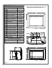
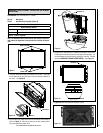
Specifications - Insert Dimensions ...................................Page 8
Clearances to Combustibles ..............................................Page 9
Installation ........................................................................Page 10
Fireplace Requirements ...............................................Page 10
Venting Requirements .................................................Page 11
Insert Leveling ............................................................. Page 12
Door Assembly Installation
or Removal Instructions ..........................................Page 13
Refractory Brick Panel Installation Instructions ...........Page 14
Log Set Installation Instructions .................................. Page 15
Surround Installation Instructions ...............................Page 17
Gas Line Installation ..........................................................Page 19
Gas Pressure Requirements ........................................Page 19
LP and Natural Gas Supplies ....................................... Page 19
Attaching Safety In Operation Warnings ........................... Page 20
Operating Instructions ...................................................... Page 21
Pre-Lighting Checklist .................................................Page 21
Lighting Instructions ...................................................Page 21
To Turn Gas Off to Appliance .......................................Page 22
Shutdown Procedure ...................................................Page 22
Flame Appearance and Sooting ...................................Page 23
Air Shutter Adjustment ................................................Page 23
Burn-In Period .............................................................Page 24
Quiet Operation ............................................................Page 24
Blower Operation and Wiring Diagram ........................Page 24
Shoreline™ Main Burner Operation ..............................Page 25
Millivolt Control System and Wiring Diagram .............. Page 25
Maintenance and Servicing ...............................................Page 26
Maintenance Checklist ................................................. Page 26
Blower Removal ...........................................................Page 26
Glass Maintenance .......................................................Page 27
Door Removal ..............................................................Page 27
Paint Touch-Up ............................................................Page 27
Inspecting Wiring ........................................................ Page 27
Fuel Conversion Kits .................................................... Page 27
Maintenance Schedule .................................................Page 28
Troubleshooting ................................................................Page 29
Replacement Parts List. ....................................................Page 30
Part Identification .............................................................. Page 31
Optional Accessories .........................................................Page 36
Safety / Listing Label .........................................................Page 39
Lighting Instructions Label ............................................... Page 40
Warranty and Product Reference Information ...................Page 42
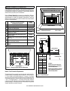
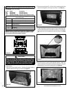
PACKAGING LIST
To install a Shoreline insert, an insert body, refractory brick panel set
and surround kit are required (each sold separately. See Page 37 for
ordering information).
Fireplace Insert Body Packaging List
Model: Shoreline 33/40 DV INS
1) Fireplace Insert Body ...................... 1) 150 cfm Blower
with Burner Cassette
......................1) 5-Piece Log Set
1) Gas pipe (3/8” x 8”) ........................ 1) Optional Shoreline #33 orifice
1) Installation and Operation Manual .. 1) Bag of Decorative Lava Rock
1) Bag of Glowing Ember Material ...... 1) Fireplace Warning Label
1) Front Leveling Leg Kit
Refractory Brick Panel Sets - 6 pieces:
Standard
Red
Architectural Stone
Surround Kits:
Small 3-sided - 36-5/8” Wide x 25-7/8” High (930 mm x 657 mm)
Large 3-sided - 41” Wide x 28” High (1041 mm x 711 mm)
Small 4-sided - 36-5/8” Wide x 29-3/16” High (930 mm x 741 mm)
Large 4-sided - 41” Wide x 33-1/2” High (1041 mm x 851 mm)
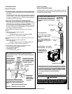
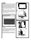
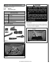
INTRODUCTION
The Insert models covered in this manual are direct-vent sealed com-
bustion gas heaters designed for residential application for installation
into an existing masonry or factory built solid fuel burning fireplace. The
required liners for the air intake and exhaust are as follows:
• Air Intake: Use 3” diameter UL 181 or UL 1777 listed liner only.
• Exhaust: Use 3” diameter UL 1777 listed gas vent liner only. DO
NOT USE UL 181 LISTED LINER.
This appliance is suitable for installation into masonry or factory built
fireplaces.
These vent systems must be routed through the existing fireplace flue
system to the vent termination.
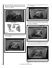
Installation Options
• .Residential • Manufactured (mobile) home
• .Bedrooms • Commercial
Your direct-vent Insert is designed to be vented vertically with a minimum
height of 10 feet and maximum of 35 feet from top of the flue collar using
natural gas or propane gas (LP).
USING THIS MANUAL
Please read and carefully follow all of the instructions found in this
manual. Please pay special attention to the safety instructions provided
in this manual.
PRODUCT IS SUBJECT TO CHANGE WITHOUT NOTICE