


WIRING DIAGRAMS
PAGE 22
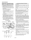
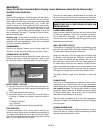
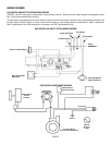
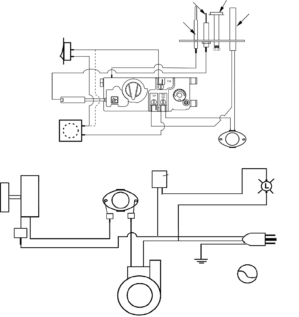
GAS CONTROL AND SAFETY SYSTEM WIRING DIAGRAM
CAUTION: Label all wiring prior to disconnection when servicing controls. Wiring errors can cause improper and dangerous opera-
tion. Verify proper operation after servicing.
The gas control wiring diagram shown here should be used by service technicians for guidance when troubleshooting problems with
the pilot safety (millivolt) system or burner remote control system or when locating system components for repair / replacement.
Note: If replacement of any of the original wire is necessary, use 105°C thermoplastic wiring.
GAS CONTROL AND SAFETY SYSTEM WIRING DIAGRAM
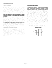
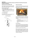
CIRCULATING BLOWER WIRING DIAGRAM
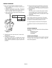
Thermocouple
Thermopile
PILOT
ASSEMBLY
Burner On/Off Switch
Wall Thermostat
(Optional)
V
ent Spill Switch
(High Limit Disc)
Igniter Electrode
Pilot Hood
V
ariable Speed
Control
(rheostat)
Thermostatic
Switch (fan disc)
Microswitch for
Control Panel Light
Control
Panel
Light
Ground
Power Cord
120 V AC
AC Power
Supply
Convection Blower
(room air circulation blower)