INSTALLATION
PAGE 15
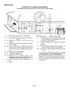
INSTALLATION CHECK LIST
Read and understand these instructions before using
appliance. Go through this installation checklist:
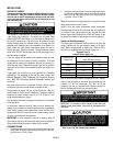
Ensure that the log set is properly installed. Use cau-
tion when handling the logs. See page 12.
Reinstall the door frame assembly. See Door As-
sembly on page 14.
WARNING: Do not operate appliance with the
glass front removed, cracked or broken. Re-
placement of the glass should be done by a
qualified technician.
Ensure venting termination cap is unobstructed.
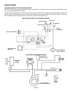
Check to see that wiring is correct and is enclosed
inside the stove pedestal base (See page 21).
Ensure that the 3 relief doors on the back and sides
of the appliance are properly closed (see Combus-
tion Chamber Relief Doors on page 16).
Verify that the gas line has been purged of air.
Test all connections for leaks (factory and field) with
a leak detector or soapy water solution. If you smell
gas, do not attempt to light this appliance. Follow
safety instructions on the front cover of this manual.
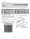
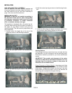
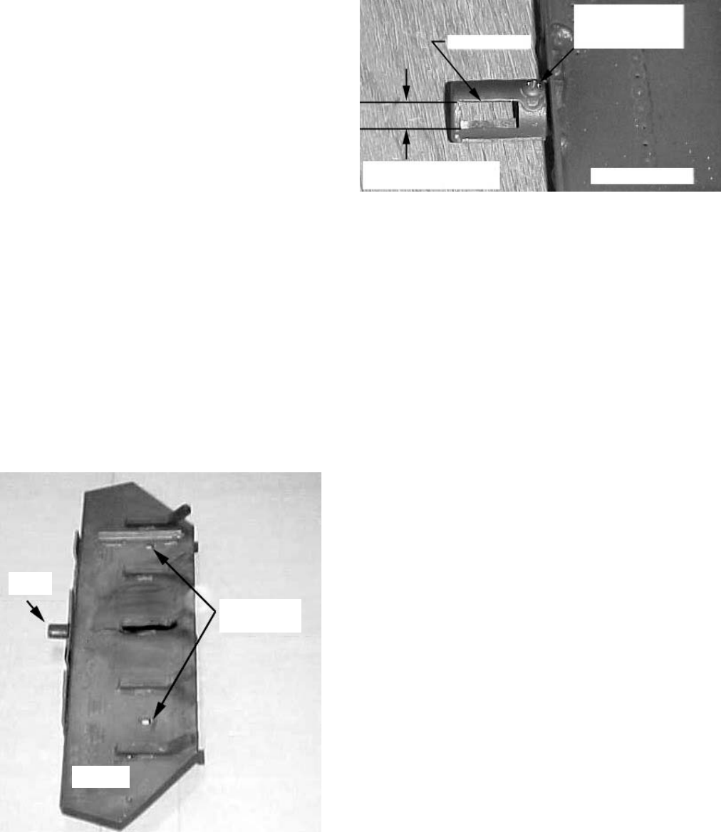
Burner Air Shutter opening to be:
Natural Gas – 1/2 open, Propane 3/4 open.
Some adjustment from standard may be necessary
for the desired flame characteristics (see Burner
Flame Appearance, page 20). To adjust air shutter:
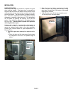
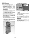
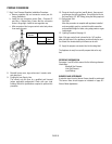
1. Remove burner from firebox by removing the 2
nuts as shown in the following picture. Then lift
burner up and out of firebox.
2. Adjust gap as shown in following picture.
3. Reinstall burner. Do not overtighten nuts (finger
tight only).
Light the appliance following the instructions on page
15 (Care and Operation). Relight the main burner in
both the HI, and LO positions, and verify proper
burner ignition and operation.
NOTE: Upon the initial firing of your new gas stove,
you may notice an odor. This may last up to two
hours. It is recommended to open the windows to al-
low fresh air to circulate into the room.
WARNING: If the pilot does not light after 1 min-
ute, wait at least 5 minutes for gas to clear before
attempting again.
With burner lit, check to make sure that the inlet gas
and manifold pressures are correct (see Gas Pres-
sure, page 4). Verify that the pilot and main burner
ignition and operation are correct.
Plug blower power cord into an 120 V, 60Hz,
grounded outlet (See Air Circulation Blower, Page 4).
Remove 2 nuts,
Then lift burner
out of firebox
Burner
Assembly
Air
Shutter
A
ir Shutter
Loosen setscrew
using Phillips
screwdriver
Burner Assembl
y
NG = 1/2 Open (1/4” gap)
LP = 3/4 Open (3/8” gap)


