


9
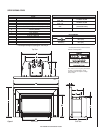
NOTE: DIAGRAMS & ILLUSTRATIONS NOT TO SCALE.
Direct Vent System Components
The following "Security Secure Vent
TM
" or "Simpson Dura-Vent" brand
Collinear Direct-Vent components may be safely used with these appli-
ances (see Figures 14 & 15).
WARNING: Do not substitute the heat-rated fl ex liner (UL1777)
for the Exhaust with any other type liner or a fi re may result
causing property damage, personal injury or loss of life.
IMPORTANT NOTES:
• Adjust Leveling Bolts if Necessary: Two leg leveling bolts are installed
into existing holes in the bottom rear of appliance. Turn the leveling bolts
to adjust for correct height.
• Refer to Vent Manufacturer Installation Instructions.
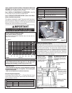
Step 7: INSTALL LP CONVERSION KIT (IF NECESSARY) - Install the
LP conversion kit per instructions provided with kit.
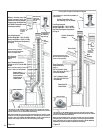
This appliance is designed to using 3” diameter UL1181 listed alumi-
num liner for the Air Intake and 3” diameter UL1777 listed gas vent
liner for the Exhaust (see Figures 14 & 15). See Table 8 for miniumum
distances from roof to termination cap inlet/outlet.
Figure 12
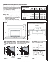
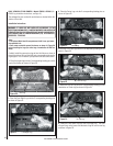
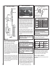
Step 8: VENTING SYSTEM INSTALLATION (Refer to Vent Manu-
facturer Installation Instructions)
Vertical Termination Height Minimum
(Factory Built and Masonry Fireplaces)
The vent/air intake termination clearances above the high side of an
angled roof is as follows:
8 (2.4)
7 (2.1)
6 (1.8)
5 (1.5)
4 (1.2)
3 (0.9)
2 (0.6)
1 (0.3)
0 (0.0)
2/12
4/12
6/12
8/12
10/12
12/12
14/12
16/12
18/12
Table 8
Feet (meters)
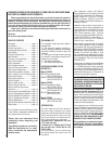
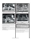
STEP 6: REMOVE PACKAGED MATERIALS FROM INSIDE FIREBOX AND
SET ASIDE (
log set, bag of embers, bag of vermiculite, propane
conversion kit - if needed to run on LP gas).
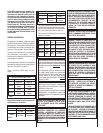
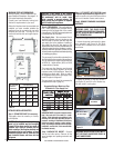
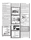
Exhaust
Intake
Liner Connec-
tor Plate
Screw
Guide
Hose
Clamps
After liners are secured to collars, slide liner con-
nector plate forward and secure with screw.
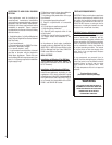
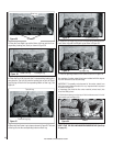
Flex Liner Installation:
Air Inlet Liner
(for combus-
tion air) When
terminating the
air inlet liner
at this point,
a positive fl ue
connection is
required (to
ensure com-
bustion air is
drawn down
the chimney
only).
Exhaust 3" (75mm)
UL 1777. A full length
liner is required from
the exhaust outlet on
appliance to center collar
of termination cap.
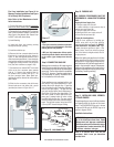
Positive Flue Connection (acceptable methods for sealing chimney throat)
Masonry and Factory Built Fireplaces
A qualifi ed installer should evaluate the existing fi replace to determine the
best method for achieving a positive fl ue connection between the vent and
intake liners and the chimney. The most common method is to secure a
noncombustible seal-off plate (i.e. 22-gage sheet steel) in the fi replace
throat using masonry screws. Other acceptable methods include packing
noncombustible material (i.e. rockwool) around the liners. Whichever
“seal off” method is used must effectively seal the area to prevent room
air passage to the chimney of the fi replace.
Positive Flue Connec-
tion (sealing fi replace
throat using a noncom-
bustible seal-off plate
or insulation).
Figure 13
The outside air inlet does not
require a full reline (if intake liner
is terminated in chimney and a
positive fl ue connection is achieved
as specifi ed).
Air Inlet
Exhaust
Air Inlet
Existing Fireplace Flue
(chimney)
Roof Pitch
Masonry and Factory
Built Fireplaces
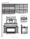
Simpson Dura Vent Components
Part No. Description
980
Termination Cap, Standard
991
Termination Cap, High Wnd
923GK
Chimney Liner Term. Kit
2280
Liner, Flex, 3” Dia. /. 35 feet.
Lennox Hearth Products – Collinear Direct-Vent Kits
Cat. No. Model Description
H0908
TKDVI
Termination Kit, DVI
H0909
FKDVI
Flex Kit, DVI 3" X 35'
Table 9a
Table 9b