


NOTE: DIAGRAMS & ILLUSTRATIONS NOT TO SCALE.
3
These appliances and their individual shut-off
valves must be disconnected from the gas supply
piping system during any pressure testing of
that system at pressures greater than 1/2 psig
(3.5 kPa).
These appliances must be isolated from the
gas supply piping system (by closing their
individual manual shut-off valve) during any
pressure testing of the gas supply piping
system at test pressures equal to or less than
1/2 psig (3.5 kPa).
NE PAS SE SERVIR DE CET APPAREIL S'IL A
ÉTÉ PLONGÉ DANS L'EAU, COMPLÈTEMENT
OU EN PARTIE. APPELER UN TECHNICIEN
QUALIFIÉ POUR INSPECTER L'APPAREIL ET
REMPLACER TOUTE PARTIE DU SYSTÈME DE
CONTRÔLE ET TOUTE COMMANDE QUI ONT
ÉTÉ PLONGÉS DANS L'EAU.
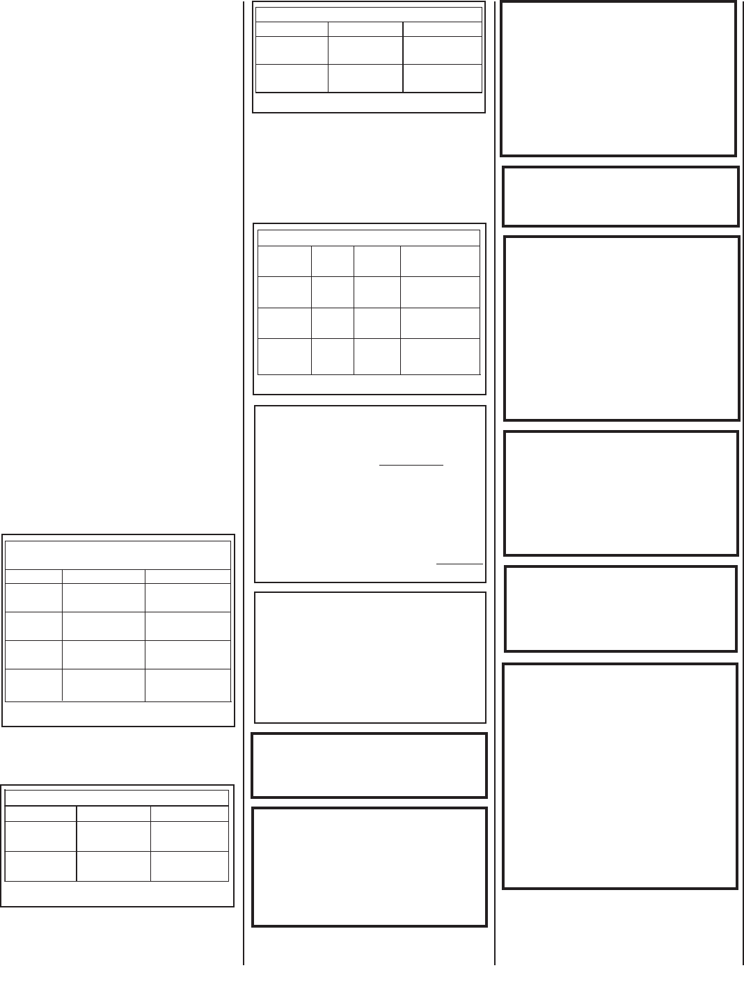
Table 4
Table 1
Table 1 shows the BTU input for each
model:
These appliances may be installed in an after-
market permanently located, manufactured
home (USA only) or mobile home, where not
prohibited by local codes.
Cet appareil peut être installé dans un maison
préfabriquée (É.-U. seulement) ou mobile déjà
installée à demeure si les réglements locaux le
permettent.
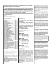
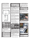
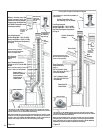
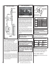
Test gauge connections are provided on the
front of the millivolt gas control valve (identi-
fi ed IN for the inlet and OUT for the manifold
side). See Figure 36a & 36b on page 14.
Tables 2 and 3 show the units' gas pressure
requirements for all models:
GENERAL INFORMATION
The appliance installation, repair and annual
inspection should be performed by a qualifi ed
service person. It is imperative that the control
compartment, burner and circulating air pas-
sage way of the appliance be kept clean.
S'assurer que le brùleur et le compartiment
des commandes sont propres. Voir les
instructions d'installation et d'utilisation qui
accompagnent l'appareil.
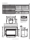
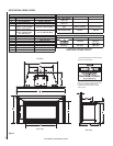
Provide adequate clearances and adequate
accessibility clearance for service and proper
operation (see table 5 on page 7).
THESE APPLIANCES MUST NOT BE CON-
NECTED TO A CHIMNEY OR FLUE SERV-
ING A SEPARATE SOLID FUEL BURNING
APPLIANCE.
WARNING: FAILURE TO COMPLY WITH THE
INSTALLATION AND OPERATING INSTRUCTIONS
PROVIDED IN THIS DOCUMENT WILL RESULT
IN AN IMPROPERLY INSTALLED AND OPERAT-
ING APPLIANCE, VOIDING ITS WARRANTY.
ANY CHANGE TO THESE APPLIANCES AND/OR
OPERATING CONTROLS IS DANGEROUS.
IMPROPER INSTALLATION OR USE OF THESE
APPLIANCES CAN CAUSE SERIOUS INJURY OR
DEATH FROM FIRE, BURNS, EXPLOSION OR
CARBON MONOXIDE
POISONING.
CARBON MONOXIDE POISONING: EARLY
SIGNS OF CARBON MONOXIDE POISONING
ARE SIMILAR TO THE FLU WITH HEAD-
ACHES, DIZZINESS AND/OR NAUSEA. IF
YOU HAVE THESE SIGNS, OBTAIN FRESH
AIR IMMEDIATELY. TURN OFF THE GAS
SUPPLY TO THE APPLIANCE AND HAVE
IT SERVICED BY A QUALIFIED PROFES-
SIONAL, AS IT MAY NOT BE OPERATING
CORRECTLY.
WARNING: DO NOT PLACE CLOTHING OR
OTHER FLAMMABLE MATERIALS ON OR
NEAR THESE APPLIANCES.
WARNING: CHILDREN AND ADULTS SHOULD
BE ALERTED TO THE HAZARDS OF HIGH
SURFACE TEMPERATURES. USE CAUTION
AROUND THE APPLIANCE TO AVOID BURNS
OR CLOTHING IGNITION. YOUNG CHILDREN
SHOULD BE CAREFULLY SUPERVISED
WHEN THEY ARE IN THE SAME ROOM AS
THE APPLIANCE
.
AVERTISSEMENT: SURVEILLER LES
ENFANTS. GARDER LES VÊTEMENTS,
LES MEUBLES, L'ESSENCE OU AUTRES
LIQUIDES À VAPEUR INFLAMMABLES À
COTE DE L'APPAREIL.
DO NOT USE THESE APPLIANCES IF ANY
PART HAS BEEN UNDER WATER. IMMEDI-
ATELY CALL A QUALIFIED, PROFESSIONAL
SERVICE TECHNICIAN TO INSPECT THE
APPLIANCES AND TO REPLACE ANY PARTS
OF THE CONTROL SYSTEM AND ANY GAS
CONTROLS WHICH HAVE BEEN UNDER
WATER.
Table 4 shows the units gas orifi ce size for the
elevations indicated.
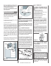
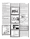
The millivolt appliances are manually con-
trolled and feature a spark igniter (piezo)
that allows the appliance's pilot gas to be
lit without the use of matches or batteries.
This system provides continued service in the
event of a power outage. However, the heat
circulation blower requires 120 volt power
(the appliance can be safely used with the
blower turned off). The blower operation is
controlled by a variable speed rheostat located
on the left side surround panel (if optional
surround is installed) and temperature switch
located underneath of fi rebox bottom on the
front left side.
Inlet Gas Supply Pressure (all models)
Fuel Minimum Maximum
Natural Gas
4.5” WC
(1.12 kPa)
10.5” WC
(2.61 kPa)
Propane
11.0” WC
(2.73 kPa)
13.0” WC
(3.23 kPa)
Table 2
Manifold Gas Supply Pressure (all models)
Fuel Low High
Natural Gas
(LO) 1.6” WC
(.40 kPa)
(HI) 3.5” WC
(.87 kPa)
Propane
(LO) 6.3” WC
(1.57 kPa)
(HI) 10” WC
(2.49 kPa)
Table 3
WARNING: THESE APPLIANCES MUST BE
PROPERLY CONNECTED TO A VENTING
SYSTEM. OPERATION OF THESE GAS
APPLIANCES WHEN NOT CONNECTED TO
A PROPERLY INSTALLED AND MAINTAINED
VENTING SYSTEM CAN RESULT IN CARBON
MONOXIDE (CO) POISONING AND POSSIBLE
DEATH.
Natural Gas Propane
Model #
Input rate
(BTU/HR)
Input rate
(BTU/HR)
EDVI30
21,500 to
30,000
22,000 to
28,000
EDVI35
25,500 to
35,000
26,000 to
34,000
EDVI25
17,000 to
25,000
19,000 to
25,000
Millivolt Models with
Manually-Modulated Gas Valves
Main Burner Orifice Size
Model # Nat.
Gas pane
Pro- Elevation
Feet (meters)
EDVI30
#37
1/16"
0-4500'
(0-1370 meters)
EDVI35
#33
(.113")
#51
(.067")
0-4500'
(0-1370 meters)
(.0625")
(.104")
EDVI25
#41
0-4500'
(0-1370 meters)
(.096")
#53
(.0595")