


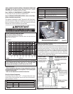


NOTE: DIAGRAMS & ILLUSTRATIONS NOT TO SCALE.
16
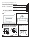
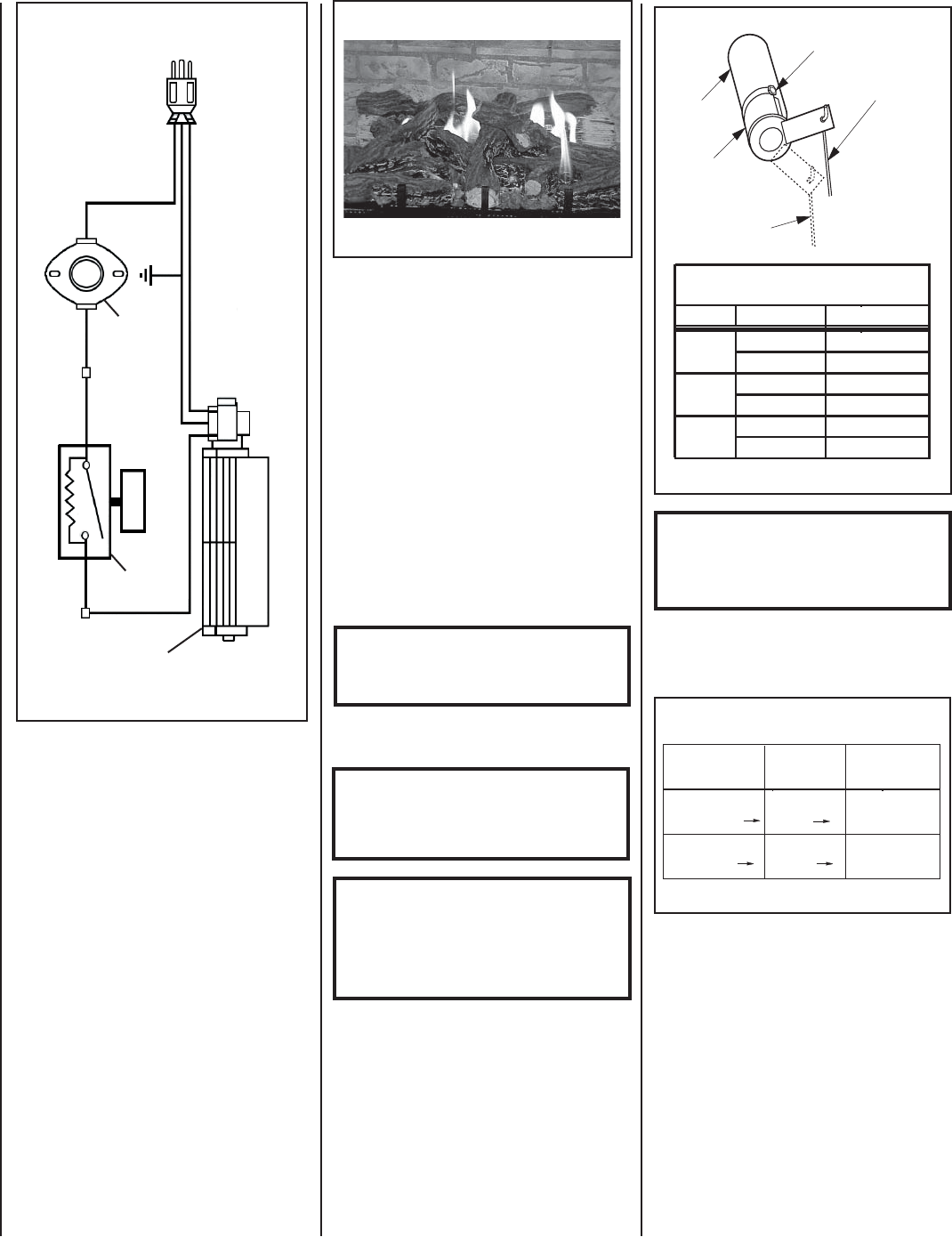
Table 10
Burner Flame Appearance
FACTORY AIR SHUTTER SETTING
INCHES (MILLIMETERS)
Models Gas Type Air Shutter Gap
Natural Gas
EDVI25
Propane
Natural Gas
5/16" (7.94 mm)
3/16" (4.76 mm)
EDVI30
Propane
1/2" (12.7 mm)
Natural Gas
3/8" (9.52 mm)
EDVI35
Propane
1/2" (12.7 mm)
3/8" (9.52 mm)
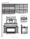
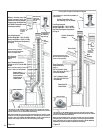
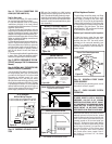
Figure 42
Burner Air Shutter Adjustment
Adjustment Rod Up
(1/8" Open Position)
Air Shutter
Burner Tube
Adjusting Set Screw
Adjustment Rod Down
(full open position)
.
Initially, always position the air shutter to the
factory setting as shown in Figure 42 (adjust-
ment rod is located in the lower control area).
This can be done by moving the adjustment
rod up or down accordingly. Allow the burner
to operate for at least 15 minutes. Observe
the fl ame continuously. If it appears weak
or sooty as previously described, adjust the
air shutter to a more open position until the
proper fl ame appearance is achieved.
IMPORTANT: ENSURE THAT THE FRONT
GLASS PANEL IS IN PLACE AND SEALED
DURING ADJUSTMENT.
CAUTION: THE ADJUSTMENT ROD AND
NEARBY APPLIANCE SURFACES ARE
HOT. EXERCISE CAUTION TO AVOID
INJURY WHILE ADJUSTING FLAME
APPEARANCE.
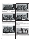
Step 18. BURNER ADJUSTMENT
Flame Appearance and Sooting
When satisfi ed that the appliance operates
properly, proceed to fi nish the installation.
Leave the control knob in the ON position and
the on/off switch in the OFF position.
Sooting is indicated by black puffs developing
at the tips of very long orange fl ames. Sooting
results in black deposits forming on the logs,
appliance inside surfaces and on exterior
surfaces adjacent to the vent termination.
Sooting is caused by incomplete combus-
tion in the fl ames and lack of combustion air
entering the air shutter opening. To achieve
a warm yellow to orange fl ame that does not
soot, the shutter opening must be adjusted
between these two extremes.
No smoke or soot should be present. Repo-
sition the logs if fl ames impinge on any of
them. If the logs are properly positioned
and sooting conditions exist, the air shutter
opening on the main burner tube should be
adjusted.
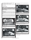
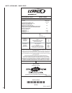
Figure 41
The following chart (Table 10) is provided to
aid you in achieving the correct air shutter
adjustment for your installation.
Air Shutter Adjustment Guidelines:
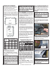
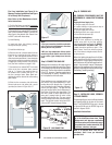
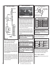
Figure 40
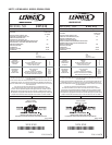
Fan Disc
Rheostat
Blower
Assembly
Power Cord
White
(Neutral)
Green
Black
Hot (Live)
RedBlackBlack
Black
120 V AC
Blower Wiring Diagram
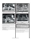
Burner Adjustment Procedure
Proper fl ame appearance is a fl ame which
is blue at the base and becomes yellow /
orange in the body of the fl ame. When the
appliance is fi rst lit, the entire fl ame may be
blue and will gradually turn yellow/orange
during the fi rst 6-8 minutes of operation. If
after 6-8 minutes the fl ame stays lowered
blue, or if the fl ame is orange with evidence
of sooting (black tip), the air shutter may
require adjustment.
Appliances operated with air shutter open-
ings that are too large will exhibit fl ames that
are blue and transparent. These weak, blue
and transparent fl ames are termed anemic.
If the air shutter openings are too small,
sooting may develop
(Ground)
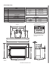
STEP 19. INSTALL LOUVER KIT
Install louver kit per the instructions provided
with the kit.
EDVI35
AIR SHUTTER ADJUSTMENT SHOULD
ONLY BE PERFORMED BY AN AUTHO-
RIZED INSTALLER AT THE TIME OF THE
INSTALLATION OR SERVICE.
CAUTION: CARBON WILL BE PRODUCED IF THE
AIR SHUTTER IS CLOSED TOO MUCH.
Any damage due to carboning resulting from
improperly setting the air shutter is NOT covered
under the warranty.
Amount of
Primary Air
Flame
Color
Air Shutter
Adjustment
If air shutter is
closed too far
Flame will be
orange
Air shutter Gap
should be
increased
If air shutter is
open too far
Air shutter Gap
should be
Decreased
Flame will be
blue