


NOTE: DIAGRAMS & ILLUSTRATIONS NOT TO SCALE.
10
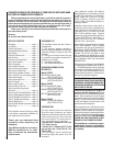
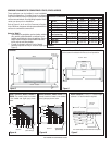
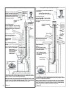
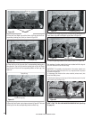
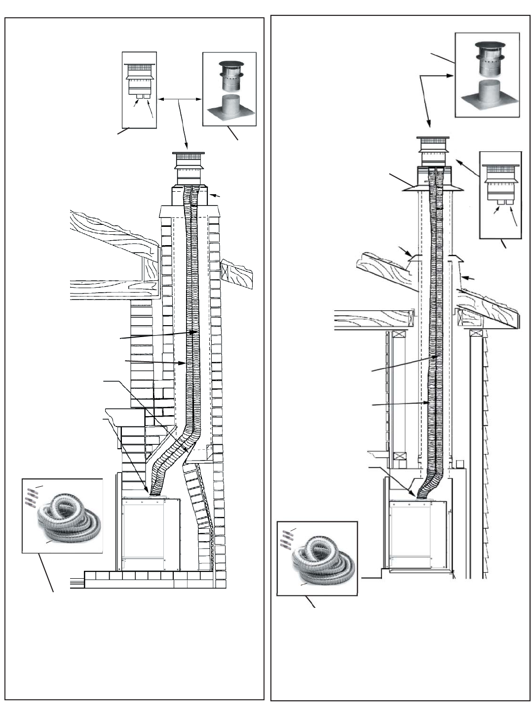
Masonry Fireplace Installation Diagram
Vertical Term-
ination Cap
and Flashing.
Cat. No.
H0908
Liner Requirements:
Vertical Height Min. = 8 ft. (2.44 M)
Vertical height Max. = 40 ft. (12.2 M)
See Direct Vent System Components
on Page 9.
Exhaust and air
Intake collars
Hook up Air
& Exhaust
as Shown
Here
Air
Intake
Exhaust
Clay
Chimney
Liner
Damper plate is
removed or fastened
in open position
Masonry chimneys may take
various contours which the
fl exible liners will accomodate.
However, keep the fl exible liner
as STRAIGHT as possible, avoid
unnecessary bending.
Figure 14
Before running the fl exible liners, make sure that both liners will pass through
existing damper area. Remove or lock damper to allow the passage of the fl exible
liners. If the damper will not allow the passage of both liners, DO NOT PROCEED
FURTHER (the appliance may NOT be installed into the fi replace).
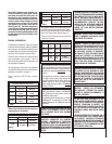
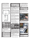
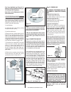
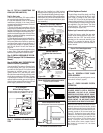
Factory Built Fireplace Installation Diagram
Vertical Termination Cap
and Flashing, Cat. No. H0908
Liner Requirements:
Vertical Height Min. = 8 ft. (2.44 M)
Vertical height Max. = 40 ft. (12.2 M)
Vertical Termination
Adapter
Storm Collar
Air
Intake
Exhaust
Exhaust and Air
Intake Collars
Hook up Air &
Exhaust as
Shown Here
Figure 15
Roof
Flashing
See Direct Vent System Components
on Page 9.
Use 3" diameter listed
liner (UL1181 or UL1777)
for the AIR INTAKE.
Use 3" diameter listed
liner (UL1777 ONLY) for
the EXHAUST
Use 3" diameter listed liner
(UL1181 or UL1777) for the AIR
INTAKE.
Use 3" diameter listed gas vent liner
(UL1777 ONLY) for the EXHAUST
The fl exible vent pipe must
NOT be allowed to sag behind
insert or in fi replace fl ue.
The fl exible vent pipe must
NOT be allowed to sag behind
insert or in fi replace fl ue.
Read fi replace
requirements,
page 4
Read Fireplace
Requirements on
page 4
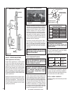
• The Flex Kit, Cat. No. H0909 includes one 35' fl ex liner and four gear clamps.
• The Termination Kit, Cat. No. H0908 includes the termination cap with two
collinear collars for 3” fl ex attachments and fl ashing.
Make sure that both liners will pass through existing damper area. Remove or lock
damper to allow the passage of the fl exible liners. If the damper will not allow the
passage of both liners, DO NOT PROCEED FURTHER. Consult a local mason for
removal of the damper without risk of structural damage or leakage.
The standard cap in Termination Kit, H0908, is a
high wind cap
The standard cap
in Termination
Kit, H0908, is a
high wind cap
• The Flex Kit, Cat. No. H0909 includes one 35' fl ex liner and four gear clamps.
• The Termination Kit, Cat. No. H0908 includes the termination cap with two collinear
collars for 3” fl ex attachments and fl ashing.
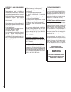
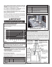
Gear Clamps
Liner
Liner
Gear Clamps