


15
NOTE: DIAGRAMS & ILLUSTRATIONS NOT TO SCALE.
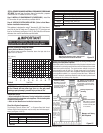
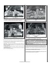
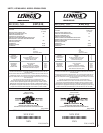
Proper Pilot Flame Appearance
O
N
O
F
F
P
I
L
O
T
L
O
H
I
Figure 36a
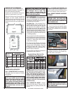
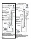
GAS CONTROL
KNOB
CONVERTIBLE
HI/LO REGULATOR
(adjusts fl ame height
and heat output)
INLET
PRESSURE
TAP
PILOT
ADJUSTMENT
SCREW
WIRING
TERM-
INALS
OUTLET
PRESSURE
TAP
MODELS: EDVI30 & EDVI35
Honeywell Gas Control Valve Diagram
TP/TH
PIEZO
IGNITER
TH
TP
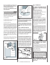
Figure 37
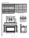
Burner On/Off Switch and Rheostat Location
If optional surround is installed
Burner On/Off
Switch
Rheostat
Left Front
Surround
Panel
Step 16. REINSTALL FRONT GLASS
DOOR ASSEMBLY.
If an optional Wall Thermostat or Remote Control
Kit was purchased, intall it now, per instructions
provided in kit. See Figure 35. I
f a wall-mounted
thermostat is selected, mount it in a con-
venient location on a wall near the insert.
Wire the thermostat within the millivolt control
circuit using a maximum of 25 feet of 18 gage,
2 conductor wire. Caution: Do not connect the
optional wall thermostat, gas control valve or
control wiring system of the unit to a 120 volt
power supply (residential line voltage).
Step 17. CHECK BLOWER SYSTEM
OPERATION
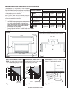
Millivolt Appliance Checkout
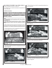
The pilot fl ame should be steady, not lifting
or fl oating. Flame should be blue in color
with traces of orange at the outer edge.
The top 3/8" (10 mm) at the pilot generator
(thermopile) and the top 1/8" minimum (tip)
of the quick drop out thermocouple should
be engulfed in the pilot fl ame. The fl ame
should project 1" (25 mm) beyond the hood
at all three ports (Figure 39).
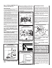
Figure 39
To reinstall glass door assembly panel, reverse
instructions on Step 5 (page 8).
When the insert heats up, the blower will auto-
matically be turned on by the fan disc, located
under the fi rebox bottom on the front left side.
It will come on at the speed determined by the
rheostat, located on left surround panel (see
Figure 37). To adjust the blower speed, dial the
rheostat to the desired speed setting. Rotate
the dial down (clockwise), just past the click
(the fi rst ON position) for the highest speed
setting. Turning the knob further clockwise
will provide slower blower speeds. Note: If
the rheostat is not turned “on”, the blower
will not operate.
¹⁄₈" Min
(3 mm)
Thermocouple
Igniter Rod
Hood
³⁄₈" Min
(9 mm)
Thermopile
Pilot
Nozzels
Figure 35
WARNING: THE POWER CORD MUST BE
PLUGGED DIRECTLY INTO A PROPERLY
GROUNDED, 120 VOLT, 60 HZ, 3-PRONG
RECEPTACLE ELECTRICAL OUTLET. DO NOT
CUT OR REMOVE THE GROUNDING PRONG
FROM THIS PLUG. IT MUST BE ROUTED TO
AVOID CONTACT. DO NOT ROUTE POWER
CORD UNDER OR IN FRONT OF APPLIANCE.
With gas line installed run initial system
checkout before closing up the front of the
unit. Follow the pilot lighting instructions pro-
vided in the Homeowner's Care and Operation
Instructions (or pull out the instruction label
located in control compartment below glass
door assembly).
Step 15. CHECKING APPLIANCE OPERA-
TION
Step 13. INSTALL SURROUND KIT OR CON-
TROL KIT (see pages 12 & 13 in Homeowners
Manual).
Step 14. INSTALL WALL THERMOSTAT AND
REMOTE CONTROL (if purchased)
To light the burner, rotate the gas valve
control knob counterclockwise to the “ON”
position then turn “ON” the on/off switch
mounted on the surround assembly (see
Figure 37) or operate the burner with the
optional remote control, wall thermostat or
control switch.
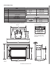
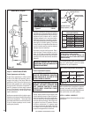
Control Compartment Access
Pull down hinged door to access control compartment
Pull down lower
louver (hinged)
Side View of Insert
Figure 38
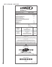
If any of the original wire as supplied must be replaced,
it must be replaced with Type AWM105°C – 18 GA. wire.
Thermopile
TH
TP
TH
TP
* ON/OFF SWITCH, OPTIONAL
THERMOSTAT
OR REMOTE
* SWITCH
CONTROL RECEIVER
SIT & Honeywell
Millivolt Wiring Diagram
H
I
L
O
W
TPTH TP TH
P
I
L
O
T
P
I
L
O
T
O
N
it
O
F
F
IN
OUT
Figure 36b
MODEL EDVI25
SIT Millivolt Gas Valve Controls
GAS CONTROL
KNOB
INLET
PRESSURE
TAP
OUTLET
PRESSURE
TAP
CONVERTIBLE
HI/LO REGULATOR
(adjusts fl ame height
and heat output)
PIEZO
IGNITER
Replace logs if removed for pilot inspection.
B. Light the appliance (refer to the lighting
instructions provided in the insert control
compartment and the Homeowner's Care and
Operation Instructions).
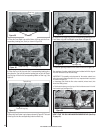
C. Brush all joints and connections with the
soapy water or leak detection solution to check
for leaks. If bubbles are formed, or gas odor is
detected, turn the gas control knob to the “OFF”
position and close the gas shut-off valve. Either
tighten or refasten the leaking connection and
retest as described above.
D. When the gas lines are tested and leak free,
observe the individual tongues of fl ame on
the burner. Make sure all ports are open and
producing fl ame evenly across the burner. If
any ports are blocked, or partially blocked,
turn off unit, allow it to cool, then clean out
the ports.
E. Turn on gas supply and test for gas leaks using
a soapy water or gas leak detection solution.
Never use an open fl ame to check for leaks.
Step 12. TEST ALL CONNECTIONS FOR
LEAKS (FACTORY AND FIELD).
Test For Gas Leaks
A. Mix a 50% dish soap, 50% water solution
(or use a gas leak detection solution).