


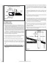
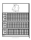
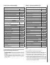
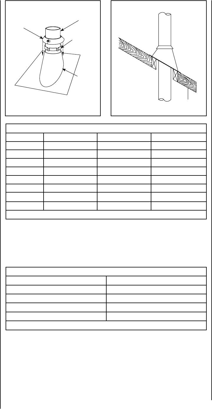
Roof Down Slope Hole Size
SLOPE ASHT / HT6103+ S-2100+ / HT6000+ AC
Roof Pitch 6” 6” 6”
0 * 12-3/8” (314 mm) 14-1/8” (359 mm) 15” (380 mm)
2/12 12-9/16” (319 mm) 14-3/8” (365 mm) 15 3/8” (390 mm)
4/12 13” (330 mm) 14-7/8” (378 mm) 16 1/8” (410 mm)
6/12 13-7/8” (352 mm) 15-3/4” (400 mm) 16 7/8” (430 mm)
8/12 14-7/8” (378 mm) 17” (432 mm) 18 1/4” (465 mm)
10/12 16-1/8” (410 mm) 18-3/8” (467 mm) 19 5/8” (500 mm)
12/12 17-1/2” (445 mm) 20” (508 mm) 21 3/8” (545 mm)
Table 3 * Cross Slope Hole Size
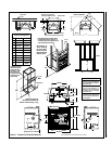
Figure 21
Figure 22
Figure 31
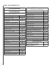
Minimum Chimney Height Using Elbows
Fireplace Model Brentwood SP
Chimney Model ASHT / S2100+ / HT6103+ / HT6000+ / AC
Vertical installation 12 feet (3.66 m)
Two (2) elbows 15 feet (4.57 m)
Four (4) elbows 17 feet (5.18 m)
Table 4
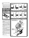
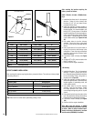
After reaching the location requiring the
elbow, proceed as follows:
ASHT / HT6103+ / S-2100+ / HT6000+ Chim-
neys
1. Install the first elbow; turn it in the required
direction. Fasten it to the chimney with
the three (3) 1/2” (12 mm) metal screws
provided with the elbow.
2. Install the necessary chimney lengths to
achieve the required offset. Lock the chimney
lengths together: it is recommended to use
three (3) 1/2” (12 mm) screws. If the offset
length is made of two (2) chimney lengths or
more, use an offset or roof support halfway
up the offset. If penetrating a wall, install
a wall radiation shield (see Figures 24 and
26).
3. Use another elbow to turn the chimney
vertically. Secure the elbow, using three
(3) 1/2” (12 mm) screws (provided with the
elbow).
4. Use a plumb-bob to line up the center of
the hole. Cut a hole for the chimney in the
ceiling/floor. Frame this hole as described
previously (refer to section Chimney Instal-
lation Instructions).
5. From below, install a firestop (See Figure
19a).
6. A support (ST or SO+) must be used on the
first 15’ section (5 m).
7. Continue with the regular installation.
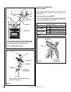
AC Chimney
1. Install the first elbow. Turn it in the required
direction. To lock it in place, turn 1/8 of a
turn. Fasten the straps attached to the elbow
to the surrounding frame, using nails or
drywall screws (Figure 25).
2. Install the necessary chimney lengths to
achieve the required offset. Lock the chimney
lengths together. If penetrating a wall, use
a wall radiation shield.
3. Use another elbow to turn the chimney
vertically. Lock it to the chimney. Fasten
the straps attached to the elbow to the
surrounding framing using nails or drywall
screws.
4. Use a plumb-bob to line up the center of the
hole. Cut a hole for the chimney in the ceiling.
Frame this hole as described previously.
5. From below, install a firestop (see Figure
19c).
6. Continue with the regular installation.
Note: When using AC chimney, an AC6SB
starter section must be used before installing
an elbow. When an offset is needed imme-
diately off the top of the fireplace, an elbow
starter section (AC6SB30) is available.
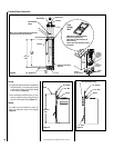
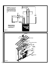
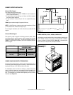
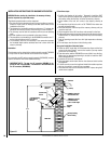
AC
Air Cooled Chimney
Collar
Chimney
Flashing
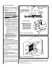
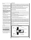
OFFSET CHIMNEY INSTALLATION
After reaching the location requiring the elbow, proceed as follows. The minimum chimney height
when using elbows is:
Spacer (built
into flashing
Note: Must return to vertical before penetrating ceiling or floor.
NOTE: DIAGRAMS & ILLUSTRATIONS ARE NOT TO SCALE.
16