


The duct system must be installed respecting
the following:
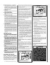
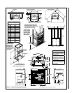
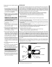
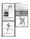
1. Remove the plates closing up the 8” dia. holes
on top of the fireplace. Then, cut the insula-
tion in order to obtain two 8” dia. openings.
Fix the adaptors on the fireplace openings
by turning clockwise (Figure 12).
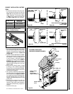
2. Maintain at least a 2” (50 mm) clearance
between the ducts and any combustible
material; the required hole size is 13” x 13”
(330 mm x 330 mm).
Exception #1: For the grills, the fram-
ing can be 10-3/4” x 10-3/4” (275 mm
x 275 mm) to provide the clearance as
required by the integral spacers on the
double outlet duct system.
3. The maximum number of elbows in a run
of duct is two.
4. Maintain at least 6-1/2” (160 mm) clearance
from the outlet grill framing to a combustible
ceiling, side wall or mantel.
5. When traversing a combustible wall or floor,
a firestop must be installed at the wall or
floor penetration. The hole size must be
13” X 13” (330 mm x 330 mm).
6. Do not connect the hot air ducts to a central
heating system. Malfunction of the heating
system’s blower will cause the fireplace to
overheat. A furnace duct is only single wall
and not double wall as is required for the
Brentwood™ fireplace hot air exhaust.
7. Use only Lennox Hearth Products grills and
components as described in this manual.
Other grills or registers, for example, may be
too restrictive and may overheat the fireplace
or ceiling.
8. Do not use insulated flexible ducts as they
will overheat.
9. Do not use tees or any other components
than the ones specifically listed here.
10. Never allow the ducting to pitch down as
hot air will be trapped creating a fire hazard.
Never route the ducting downwards.
11. The hot air outlet grills must be installed with
the louvers pointing downwards in order to
prevent overheating adjacent ceilings.
12. Always install the two outlet grills when using
the double hot air outlet kit and blocking the
upper louver of the fireplace.
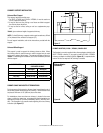
OUTSIDE AIR KIT
During operation, the fireplace requires fresh air for combustion and draws air out of the house.
It may starve other fuel burning appliances such as gas or oil furnaces. As well, exhaust blow-
ers may compete for air, causing negative pressure in the house, resulting in smoke entering the
house from the fireplace. This situation is aggravated in modern airtight houses. To overcome
this problem, we strongly recommend that you install an outside air assembly. Check with local
authorities having jurisdiction in your area, it may be mandatory.
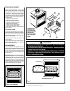
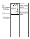
Note: Should you decide not to install the outside air assembly, proceed as follows:
- Remove the bottom grill. The air box is located on front left and is on a slant.
- Unscrew the four screws holding the inside air box covering plate and remove it.
Outside Air Installation
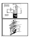
The outside air assembly may be installed according to the following requirements:
A) Duct length should be kept to a minimum. The maximum length of duct is twenty (20) feet (6.1
m) for a 4 in. dia. pipe (See note below).
B) The air intake register must not be installed more than ten (10) feet (3050 mm) above the base
of the fireplace.
C) The fresh air must come from outside the house. The air intake must not draw air from the
attic, from the basement or garage.
D) The air intake should be installed where it is not likely to be blocked by snow or exposed to
extreme wind and away from automobile exhaust fumes, gas meters and other vents.
E) The duct and register may be installed above or below floor level.
The following components are required:
- Outside air kit (UZI) (includes 40 inch flex that goes up to ten (10) feet long)
- 4” Adaptor for fireplace connection (supplied with the unit)
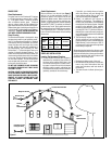
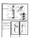
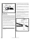
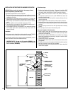
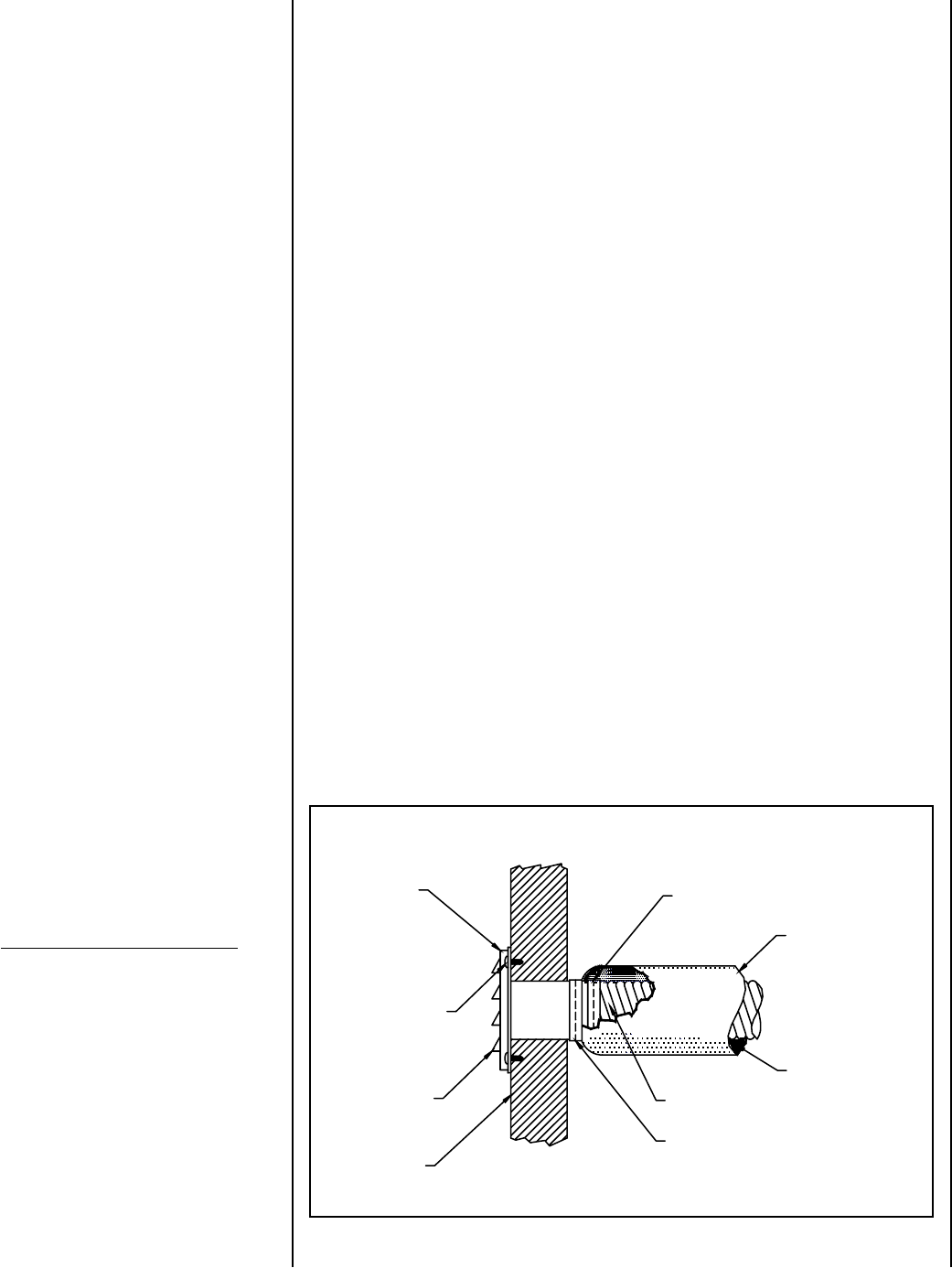
Make a 4-1/4” (110 mm) hole in the outside wall of the house at the chosen location. From outside,
place the outside air register in the hole (open side down) and fasten the register to the wall, with
screws as shown (see Figure 15). Slip the pipe into the insulated sleeve. Place the insulated pipe
over the register tube and over the fireplace’s outside air connector (see Figure 16). At each end,
carefully pull back the insulation and plastic cover exposing the flexible pipe. Using the aluminium
tape provided, wrap the tape around the joint between the flexible pipe and the air inlets. Carefully
push the insulation and plastic cover back over the pipe. Using aluminium tape, fasten the plastic
cover in place.
Note: We recommend not to exceed 20 feet of 4” flexible pipe. If you require a longer length we
recommend that you use a 5” diameter flexible pipe for the complete run up to 30 feet and a 6”
diameter pipe for a run of up to 40 feet.
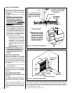
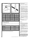
Figure 15
OUTSIDE CONNECTION
Outside
Intake
Screw
Opening
Facing
Down
Wall
Aluminum Tape
Plastic Cover
Insulation
Flexible Pipe
Aluminum Tape
NOTE: DIAGRAMS & ILLUSTRATIONS ARE NOT TO SCALE.
13