Installation
General Instructions
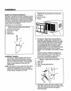
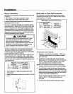
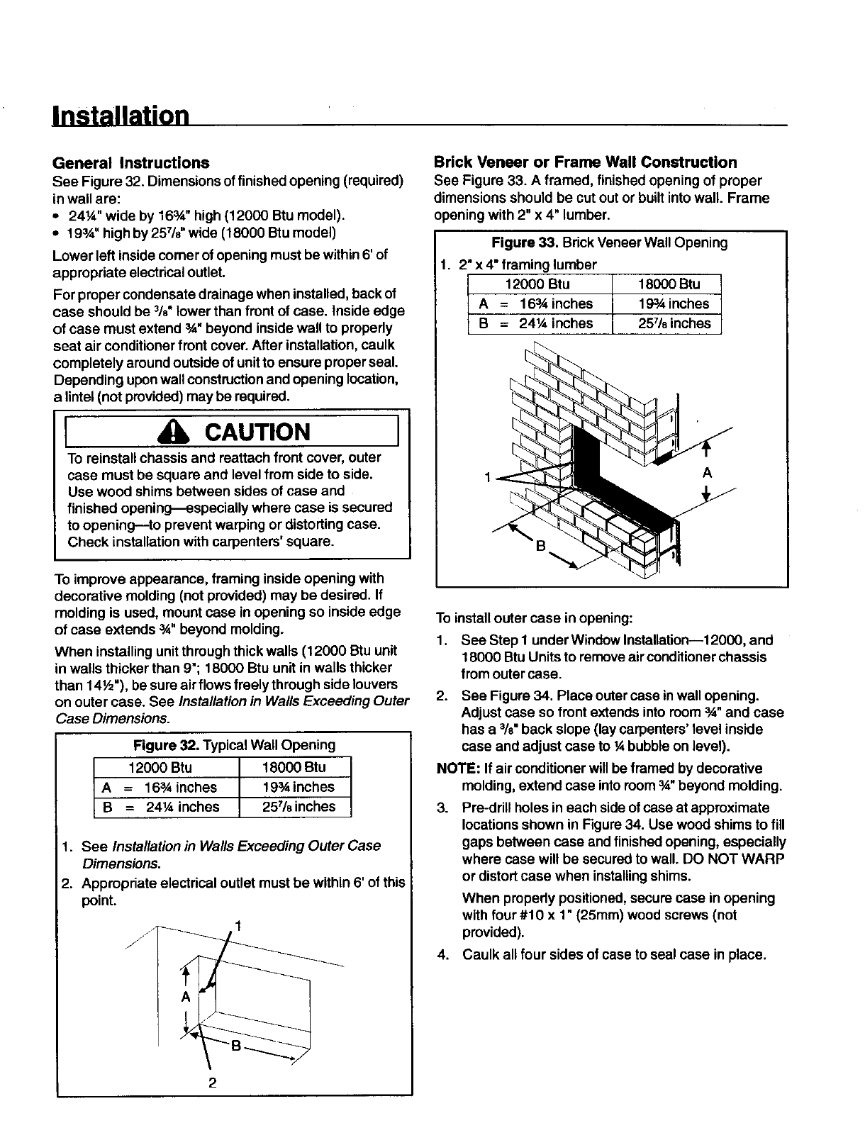
See Figure 32. Dimensions of finished opening (required)
in wall are:
• 24¼" wide by 16_" high (12000 Btu model).
• 19%" high by 257/8"wide (18000 Btu model)
Lower left inside comer of opening must be within 6' of
appropriate electrical outlet.
For proper condensate drainage when installed, back of
case should be %" lower than front of case. Inside edge
of case must extend 3,4,beyond inside wall to properly
seat air conditioner front cover. After installation, caulk
completely around outside of unit to ensure proper seal.
Depending upon wall construction and opening location,
a lintel (not provided) may be required.
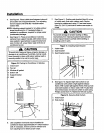
I CAUTION I
To reinstall chassis and reattach front cover, outer
case must be square and level from side to side.
Use wood shims between sides of case and
finished opening_especially where case is secured
to opening--to prevent warping or distorting case.
Check installation with carpenters' square.
To improve appearance, framing inside opening with
decorative molding (not provided) may be desired. If
molding is used, mount case in opening so inside edge
of case extends _" beyond molding.
When installing unit through thick walls (12000 Btu unit
in walls thicker than 9"; t 8000 Btu unit in walls thicker
than 14½"), be sure air flows freely through side louvers
on outer case. See Installation in Walls Exceeding Outer
"_aseDimensions.
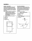
Figure 32. Typical Wall Opening
_ 12000 Btu 18000 Btu
= 16sAinches 19_inches
= 241/4inches 257/8inches
1. See Installation in Walls Exceeding Outer Case
Dimensions.
2. Appropriate electrical outlet must be within 6' of this
point.
/J
Brick Veneer or Frame Wall Construction
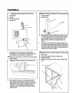
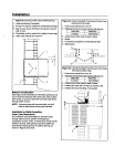
See Figure 33. A framed, finished opening of proper
dimensions should be cut out or built intowall. Frame
opening with 2" x 4" lumber.
Figure 33. Brick Veneer Wall Opening
1. 2" x 4" framing lumber
12000 Btu 18000 Btu
A = 163,4inches 193Ainches
B = 24¼ inches 25718inches
A
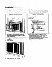
To install outer case in opening:
1. See Step I under Window Installation--12000, and
18000 Btu Units to remove air conditionerchassis
from outer case.
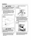
2. See Figure 34. Place outer case in wall opening.
Adjust case so front extends into room 3A"and case
has a %" back slope (lay carpenters' level inside
case and adjust case to ¼ bubble on level).
NOTE: If air conditioner willbe framed by decorative
molding, extend case intoroom3A"beyond molding.
3. Pre-drill holes in each side ofcase at approximate
locationsshown in Figure 34. Use wood shims to fill
gaps between case and finished opening, especially
where case will be secured to wall. DO NOT WARP
or distort case when installingshims.
When pmpedy positioned, secure case in opening
with four #10 x 1" (25mm) wood screws (not
provided).
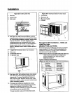
4. Caulk all four sides ofcase to seal case in place.


