


8
Questions? Call the Kenmore Water Line 1-800-426-9345 or visit www.kenmorewater.com
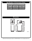
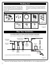
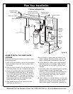
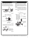
Plan Your Installation
psi, buy and install a pressure reducing valve in the
pipe supplying water to the softener’s inlet.
NOTE: If water pressure during the day is 100 psi or
more, pressure during the night may go above
125 psi.
Installation
For your water softener to work properly, incoming
water pressure in your house pipes must be no lower
than 20 pounds per square inch (psi). The highest
allowable pressure is 125 psi. If pressure is above 125
CHECK YOUR WATER PRESSURE BEFORE INSTALLING
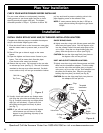
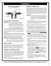
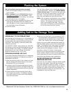
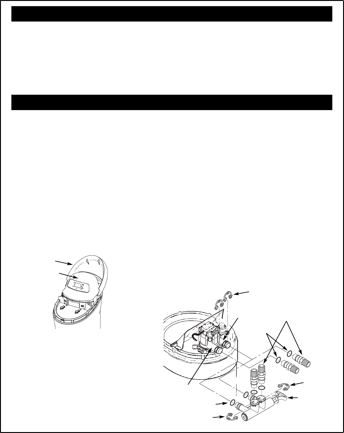
5. Visually check and remove any foreign mate-
rials from the valve inlet and outlet ports (see
Fig. 6). Carefully remove the two large plastic
clips (you will use them). Check to be sure
the turbine and support are firmly in place
(see Fig. 7).
NOTE: If you will not install the included bypass
valve because you will have a 3-valve
bypass in your plumbing, skip step 6, but
perform step 7.
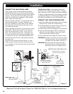
Complete the following steps to assemble the adaptors
and/or the included single bypass valve.
1. Close the shutoff valve on the house main water pipe,
near the water meter or pressure tank, to turn off the
water.
2. Shut off the gas or electric supply to the water
heater.
3. Open the highest and lowest water faucets in your
house. This will let water drain from the pipes.
Close faucets after water has drained.
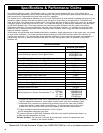
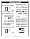
4. Remove the top cover. Pull outward on the two tabs
to release top cover (see Fig. 5). The salt lid remains
attached to the top cover when removed. Set both
covers aside so they will not get scratched or broken.
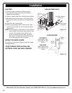
INSTALL SINGLE BYPASS VALVE AND/OR THREADED INSTALLATION ADAPTORS
SINGLE BYPASS VALVE:
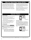
6. Lightly coat the o-rings with silicone grease and slide
them onto the bypass valve. Push the bypass valve
into the softener valve’s inlet and outlet ports as far
as it will go. Snap the two large holding clips into
place, from the top down as shown (see Fig. 8).
CAUTION: Be sure the clips snap firmly into place so
the bypass valve will not pull out.
INLET AND OUTLET THREADED ADAPTORS:
7. Lightly coat the o-rings with silicone grease and slide
them onto the installation adaptors. Push the adap-
tors into the valve inlet and outlet ports, or bypass
valve ports, as far as they will go. Both adaptors are
the same and fit either port. Snap the two large
holding clips into place, as shown (see Fig. 8).
CAUTION: Be sure the clips snap firmly into place so
the adaptors will not pull out.
Salt Lid
Top Cover
Figure 5
Single
Bypass Valve
Figure 6
Clips
Threaded
Installation
Adaptors
Valve
Outlet
Valve Inlet
Clip
O-Rings
O-Rings
Clip