


23
Questions? Call the Kenmore Water Line 1-800-426-9345 or visit www.kenmorewater.com
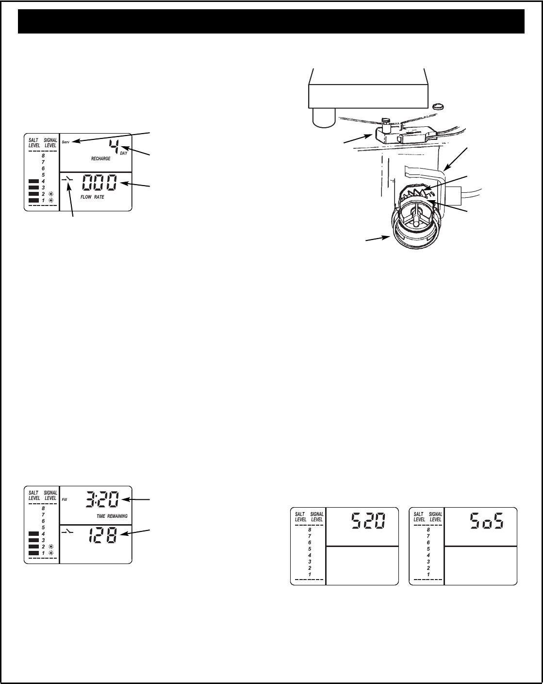
Figure 41
Figure 42
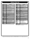
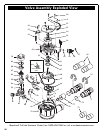
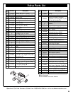
Service Information
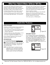
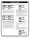
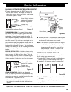
1. To enter diagnostics, press the SELECT button and
hold for three seconds. The display will change to
show turbine count, valve cycle position, and position
switch status (open or closed).
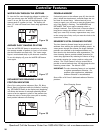
MANUALLY INITIATED ELECTRONIC DIAGNOSTICS
Number of Days since
the last Regeneration
Valve Position Indicator
Turbine Count
(No Water Flowing)
Position Switch Indicator (Open)
Minutes of Cycle (ex -
am ple: Fill) Remaining
3. Press the SELECT button, and the electronic controller
will restart.
4. Set the present time, hardness, etc., as described on
pages 13 & 14.
= Press and hold the s DOWN button to display the
number of regenerations initiated by this controller
since the model code number was entered.
NOTE: If the electronic controller is left in the diagnos-
tic display (or a flashing display when setting
times or hardness), the normal time of day dis-
play automatically returns if a button has not
been pressed for 4 minutes. To return to the
diagnostic display, repeat step 1, above.
RESETTING TO FACTORY DEFAULTS
To reset the electronic controller to its factory default
for all settings (time, hardness, etc.):
1. Press the SELECT button and hold it until the display
changes twice to show the flashing model code.
2. Press the r UP button to display a flashing “SoS”.
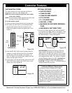
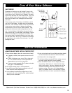
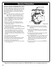
TURBINE OPERATION: If no water is flowing through
the softener, the turbine indicator displays three zeros.
When water is flowing, a 000 to 140 count repeats for
each gallon of water passing through the turbine. To
check for positive operation of the turbine if zeros are
shown, open a nearby soft water faucet and observe
the turbine count. If you don’t get a reading in the dis-
play with faucet open, pull the sensor housing from the
valve outlet port (see Fig. 43). Pass a small magnet
back and forth in front of the sensor. You should get a
reading in the display. If you get a reading, unhook the
inlet and outlet plumbing and check the turbine for
binding.
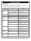
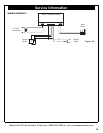
POSITION SWITCH STATUS: With the valve in service,
or any of the recharge cycle positions, the position
switch indicator will show the switch open. While the
valve is rotating from one position to another, the posi-
tion switch indicator will show the switch closed. There
is likely a problem if indications vary from this pattern.
Figure 44
OTHER INFORMATION: While in the diagnostics
screen, the following information is available and may
be beneficial for various reasons. This information is
retained by the electronic controller from the first time
electrical power is applied to the unit.
= Press and hold the r UP button to display the num-
ber of days this controller has had electrical power
applied.
Turbine Count
(Water Flowing)
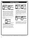
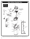
Figure 43
Motor
Turbine
Support
& Shaft
Sensor
Housing
Turbine
Valve Outlet
Position
Switch