


SECTION 5 SERVICE TECH INFORMATION
5A. TROUBLESHOOTING
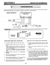
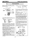
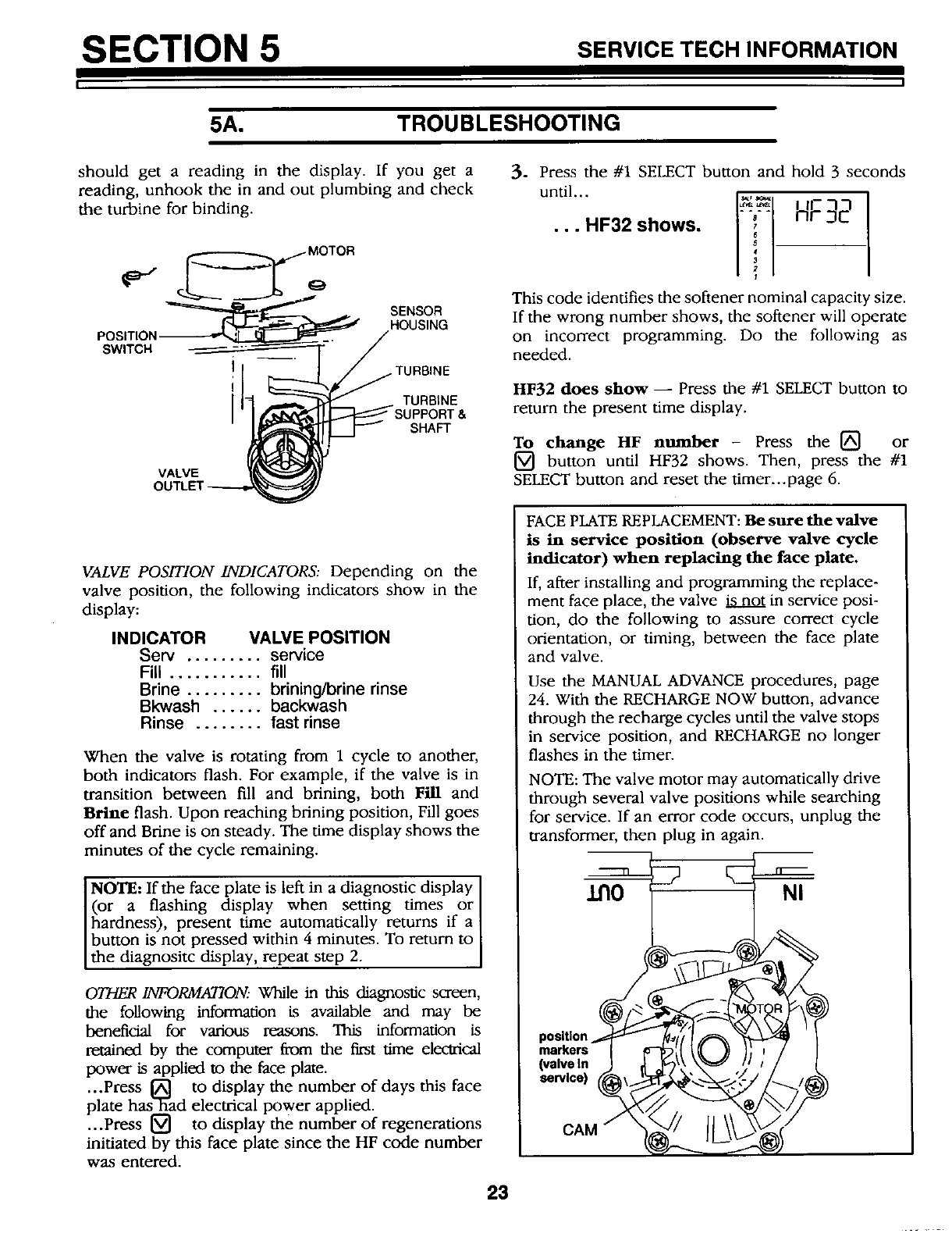
should get a reading in the display. If you get a
reading, unhook the in and out plumbing and check
the turbine for binding.
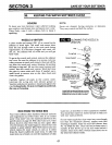
o-"
POSITION
SWITCH
MOTOR
SENSOR
HOUSING
TURBINE
TURBINE
SHAFT
VALVE
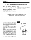
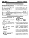
VALVE POSITION INDICATORS: Depending on the
valve position, the following indicators show in the
display:
INDICATOR VALVE POSITION
Serv ......... service
Fill ........... fill
Brine ......... brining/brine rinse
Bkwash ...... backwash
Rinse ........ fast rinse
When the valve is rotating from 1 cycle to another,
both indicators flash. For example, if the valve is in
transition between fill and brining, both Fill and
Brine flash. Upon reaching brining position, Fill goes
off and Brine is on steady. The time display shows the
minutes of the cycle remaining.
NOTE: If the face plate is left in a diagnostic display
(or a flashing display when setting times or]
hardness), present time automatically returns if a
button is not pressed within 4 minutes. To return to
the diagnositc display, repeat step 2.
OTHER INFORMATION. While in this diagnostic screen,
the following information is available and may be
beneficial for various masons. This information is
retained by the computer from the first time electrical
power is applied to the face plate.
...Press [] to display the number of days this face
plate has3_ad electrical Power applied.
...Press [_ to display the number of regenerations
initiated by this face plate since the HF code number
was entered.
23
3. Press the #1 SELECT button and hold 3 seconds
until...
...SFaashows. H; 2
This code identifies the softener nominal capacity size.
If the wrong number shows, the softener will operate
on incorrect programming. Do the following as
needed.
HF32 does show -- Press the #1 SELECT button to
return the present time display.
To change HF number - Press the [] or
[] button until HF32 shows. Then, press the #1
SELECT button and reset the timer...page 6.
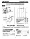
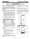
FACE PLATE REPLACEMENT: Be sure the valve
is in service position (observe valve cycle
indicator) when replacing the face plate.
If, after installing and programming the replace-
ment face place, the valve _ in service posi-
tion, do the following to assure correct cycle
orientation, or timing, between the face plate
and valve.
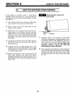
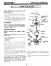
Use the MANUAL ADVANCE procedures, page
24. With the RECHARGE NOW button, advance
through the recharge cycles until the valve stops
in service position, and RECHARGE no longer
flashes in the timer.
NOTE: The valve motor may automatically drive
through several valve positions while searching
for service. If an error code occurs, unplug the
transformer, then plug in again.
11"10 NI
markers
(valve in
service)
CAM