


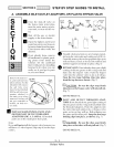
li!i! ::i:i ! ::i:i ! ::iSECTION 3 STEP BY STEP GUIDES TO INSTALL
A. ASSEMBLE INLET-OUTLET ADAPTORS, OR PLASTIC BYPASS VALVE
S
C
T
N
MJJJJJJJJJJJJJJJJ
MJJJ JJJJJJJJJJJ
MJ_dJdJdJdJd
MJ JJJJJJJJJJ
MJJJ JJJJJJJJJJ
MJ JJJJJJJJJJ
_dJ dJdJdJdJd
MJJJJJJJJJJJJJJJJ
MJJJJJJJJJJJJJJJJ
ffi
ffi
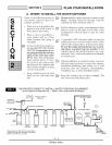
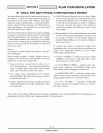
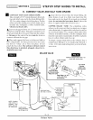
Close the shut-off valve on
the house main water pipe,
near the water meter or pres-
sure tank, to turn off the wa-
ter.
Shut off the gas or electric
supply to the water heater.
Open the highest and lowest
water faucets in your house to
let water drain from the pipes.
Close faucets after water has
drained.
If not already done, remove
all cardboard or plastic pack-
ing pieces from inside the
softener. Set the cardboard
liner (with parts for installing
fastened to it) where you can
easily see it, and get to parts
as you need them.
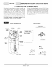
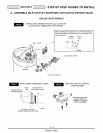
Remove the main cov-
er...putl outward on 2
tabs to release. For the
UltraSoft 100 remove
the salt hole cover
first. For the UltraSoft
200 the salt hole cover
remains attached to
the main cover when
removed. So they will
not get scratched or
broken, set both cov-
ers aside.
Salt Hole
Cover
(M_n)
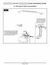
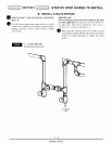
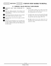
ffi INSTALL SEARS BYPASS VALVE AND /
OR THE INLET OUTLET THREADED
ADAPTORS (FIG. 4, 5 AND 6). All needed
parts are on the small parts skin-pack.
Note:
If you will not install the bypass valve because you
will have a 3- valve bypass, skip step b, but do steps
a and c.
Shutoff
-_"" -_ " Water
Meter
Pump
0
0
0
Electrical
Panel
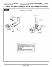
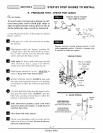
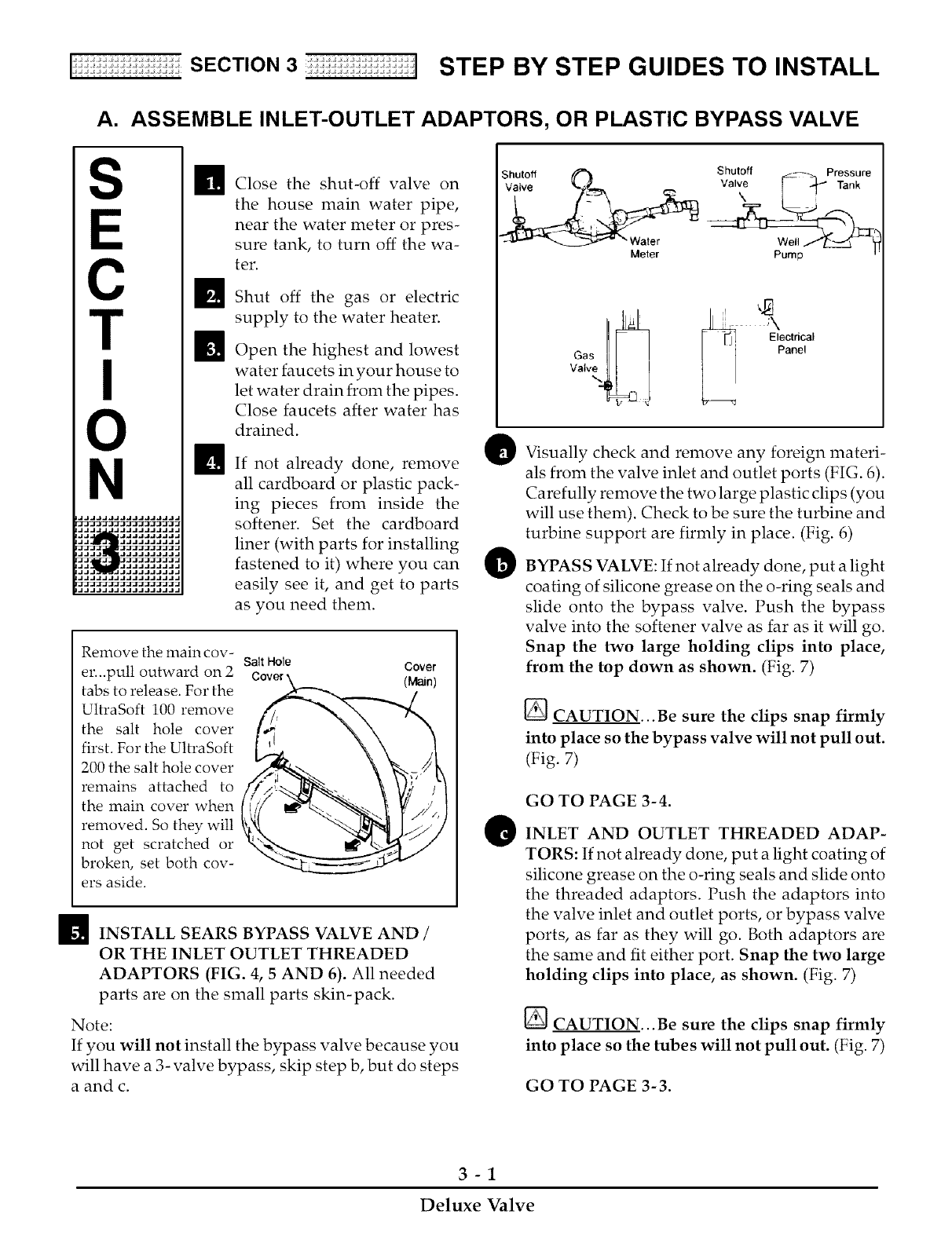
Visually check and remove any foreign materi-
als from the valve inlet and outlet ports (FIG. 6).
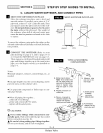
Carefully remove the two large plastic clips (you
will use them). Check to be sure the turbine and
turbine support are firmly in place. (Fig. 6)
BYPASS VALVE: If not already done, put a light
coating of silicone grease on the o-ring seals and
slide onto the bypass valve. Push the bypass
valve into the softener valve as far as it will go.
Snap the two large holding clips into place,
from the top down as shown. (Fig. 7)
[] CAUTION...Be sure the clips snap firmly
into place so the bypass valve will not pull out.
(Fig. 7)
GO TO PAGE 3-4.
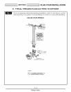
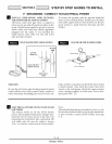
INLET AND OUTLET THREADED ADAP-
TORS: If not already done, put a light coating of
silicone grease on the o-ring seals and slide onto
the threaded adaptors. Push the adaptors into
the valve inlet and outlet ports, or bypass valve
ports, as far as they will go. Both adaptors are
the same and fit either port. Snap the two large
holding clips into place, as shown. (Fig. 7)
CAUTION...Be sure the clips snap firmly
into place so the tubes will not pull out. (Fig. 7)
GO TO PAGE 3-3.
3-1
Deluxe Valve