


Installation Instructions (cont'd)
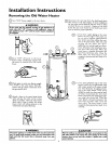
Venting (cont'd)
AWARNING of
Be sureventpipeisproperlyconnectedto preventescape
dangerousfluegaseswhichcouldcausedeadlyasphyxiation.
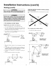
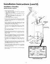
VENTING SYSTEM EXAMPLE INSTALLATIONS
FOR ALL MODELS
The vent piping cannot under any circumstances be run down-
hill.
AWARNING
Chemical vapor corrosion of the flue and vent system may
occur if air for combustion contains certain chemical vapors.
Spray can propellants, cleaning solvents, refrigerator and air
conditioner refrigerants, swimn_ing pool chemicals, calcium
and sodium chloride, waxes, bleach, and processchemicals are
typicalcompounds which are potentially corrosive.
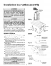
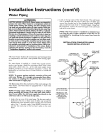
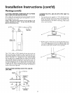
3" PVC SCHEDULE 40 VENT PIPING
Supplied in the carton with the water heater are:
1. A 3" PVC Schedule 4045 ° vent cap with wire screen.
2. A 3" PVC Schedule 40-90 ° street ell; used to connect the
vent pipe to the water heater when the vent pipe is to be
turned horizontally directly off the blower.
3. A 5' section of 3" PVC Schedule 40 pipe (more may be
required and must be supplied locally).
3" PVC SCHEDULE 40
90° ELBOW
VENT CAP
WITH SCREEN
I
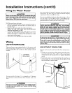
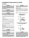
1. The water heater requires its own (separate) venting
system.
2. 3" PVC, ABS or CPVC Schedule 40 piping and fittings are
acceptable materials for the vent system on all 40 gallon
models and 50 gallon 40,000 BTU/HR models.
3. It cannot be connected to existing vent piping or
chimney.
4. It must terminate horizontally to the outdoors.
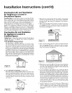
The vent piping can be installed as follows:
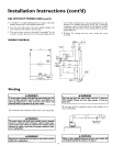
1. No more than 3 elbows can be used.
4>
MIN. RISE I/4"
PER FOOT
MAX, 3
MAX 20'
MIN. RISE i/4"
PER FOOT
16
TOTAL VERTICAL AND
HORIZONTAL RUNS
CANNOT EXCEED 35'
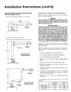
MIN. RISEI/4"
PERFOOT
TOTAL VERTICAL AND
HORIZONTAL RUNS
CANNOT EXCEED 35'