


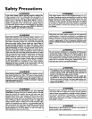

Installation Instructions (cont'd)
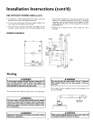
Combustion Air and Ventilation
for Appliances Located in
Unconfined Spaces
Unconfined Space is a space whose volume is not less than 50 cubic
feet per 1,000 Btu per hour of the aggregate input rating of all appli-
ances installed in that space. Rooms communicating directly with the
space in which the appliances are installed, through openings not fur_
nished with doors, are considered a part of the unconfined space.
In unconfined spaces in buildings, infiltration may be adequate to
provide air for combustion, ventilation and dilution of flue gases.
However, in buildings of tight construction (for example, weather
stripping, heavily insulated, caulked, vapor barrier, etc.), additional air
may need to be ])rovided using the methods described in Combustion
Airand Ventilation for Appliances Located in Confined Spaces.
Combustion Air and Ventilation
for Appliances Located in
Confined Spaces
Confined Space is a space whose volume is less than 50 cubic feet per
1,000 Btu per hour of the aggregate input rating of all appliances
installed in that space.
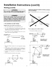
a. ALL AIR FROM INSIDE BUILDINGS:
(See Page 8 Figure 1, and Figure 5 below)
The confined space shall be provided with two permanent open-
ings communicating directly with an additional room(s) of suffi-
cient volume so that the combined volume of all spaces meets the
criteria for an unconfined space. The total input of all gas utiliza-
tion equipment installed in the combined space shall be considered
in making this determination. Each opening shall have a minimum
free area of one square inch per 1,000 BTU per hour of the total
input rating of all gas utilization equipment in the confined space,
but not less than 100 square inches. One opening shall commence
within 12 inches of the top and one commencing within 12 inches
of the bottom of the enclosure.
Figure 5 I
_L
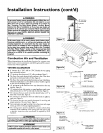
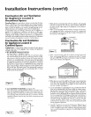
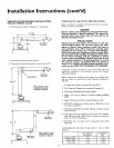
b. ALL AIR FROM OUTDOORS: (see Figures 6-8)
The confined space shall be provided with two permanent open-
ings, one commencing within 12 inches of the top and one com-
mencing within 12 inches from the bottom of the enclosure.
The openings shall communicate directly, or by ducts, with the
outdoors or spaces (crawl or attic) that freely communicate with
the outdoors.
j Figure 6 ]
, ii
\ /
_Utlt_rlO_LOUVE.S
1. When directly communicating with the outdoors, each opening
shallhave a minintum free area of 1 square inch per 4,000 BTU
per hour of total input rating of all equipment in the enclosure.
(See Figure6.)
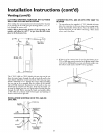
2. When communicating with the outdoors through vertical ducts,
each opening shall have a minimum free area of 1 square inch
per 4,000 BTU per hour of total input rating of allequipment in
the enclosure. (SeeFigure 7.)
Figure 7 ]
_NTILAT_N LOUVERS
{_ch cad o_a_m)
AIR OUTLEt
_VEN_ TO
_TDOO_sINLETAIn DUCT
',',',',',',',%'! i_ll:J
.......... t,,
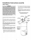
3. When communicating with the outdoors through horizontal
ducts, each opening shall have a minimum free area of 1 square
inch per 2,000 BTU per hour of total input rating of all equip-
ment in the enclosure. (SeeFigure 8.)
Figure 8 ]
OUTLET_1_ DUCT
WATER
HE_TE_
iiirlll,,,,,llll
,_,,,,_,,,rll_llll
_VENTTO
OUTDOORS
4. When ducts are used, theyshallbe of the samecross-sectionalarea
as the freearea of the openings to which they connect.The mini-
mum short side dimension of rectangular air ducts shall not be
lessthan 3 inches. (SeeFigure8.)
5. Louversand Grilles:In calculating freearea, consideration shall be
given to the blocking effect of louvers, grillesor screensprotect-
ing openings. Screens usedshall not besmaller than¼inch mesh.
If the freearea through a design of louver or grille is known, it
should be used in calculating the sizeopening required to provide
the free area specified. If the design and freearea is not known, it
may beassumed that wood louverswill be 20-25 percentfree area
and metal louvers and grilles wi!l have 60-75 percent free area.
Louvers and grilles shallbe fixed in the open _osition or inter-
locked with the equipment so that they are opened automatically
during equipment operation.
6. Special Conditions Created by Mechanical Exhausting or
Fireplaces:Operation of exhaust fans, ventilation systems,clothes
dryers or fireplacesmay create conditions requiring specialatten-
tion to avoid unsatisfactory operation of installed gas utilization
equipment.
11