


Installation Instructions (cont'd)
Temperature-Pressure Relief Valve
_,WARNING
At the time of manufacture this water heater was provided
with a combination temperature-pressures relief valvecertified
by a nationally recognized testing laboratory that maintains
Jerlodlc inspection of production of listed equipment or mate-
rials_ as meeting the requirements for Relief Valves and
Automatic Gas Shutoff Devicesfor Hot Water SupplySystems,
and the latest edition of ANSI Z21.22 and the code require-
ments of ASME. If replaced, the valve must meet the require.
ments of local codes_but not lessthan a combination tempera-
ture and pressurerelief valve certified as meeting the require-
ments for Relief Valvesand Automatic Gas Shutoff Devices for
Hot Water Supply Systems,ANSI Z21.22 bya nationally recog-
nized testing laboratory that maintains periodic inspection of
_roduction of listedequipment or materials.
The valve must he marked with a maximum set pressure not
to exceed the marked hydrostatic working pressure of the
water heater (150 Ibs.lsq.in.) and a dischargecapacity not less
than the water heater input rate as shownon the model rating
plate. (Electric heaters - watts divided by 1000 x 3415 equal
BTU/Hr. rate.)
Your local jurisdictional authority, while mandating the use of a
temperature-pressure relief valve complying with ANSI Z21.22
and ASME, may require a valve model different from the one
furnishedwith the water heater.
Compliance with such localrequirements must be satisfied by
the installer or end user of the water heater with a locally pre-
scribedtemperature-pressure relief valve installedin the desig-
nated opening in the water heater in place of the factory fur-
nishedvalve.
For safe operation ofthe water heater,the relief valvemust not
be removed from it'sdesignatedopeningor plugged.
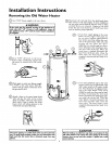
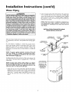
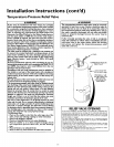
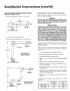
The temperature-pressure relief valve mustbe installed directly
into the fitting ofthe water heater designatedfor the relief valve.
Positionthe valve downward and provide tubing sothat any dis-
charge will exit only within 6 inchesabove, or at any distance
below the structural floor. Be certain that no contact is made
with any live electrical part. The dischargeopening mustnot be
blocked or reduced in size under any circumstances.Excessive
length, ever 30 feet, or useof more than four elbows can cause
restriction and reduce the dischargecapacityofthe valve.
No valveor other obstruction isto be placed between the relief
valve and the tank. Do not connect tubing directly to discharge
drainunlessa 6" air gapisprovided.To preventbodilyinjury, haz.
ardto life,or property damage, the relief valve must be allowed
to dischargewater in quantitiesshouldcircumstancesdemand. If
the dischargepipe isnot connected to a drain or other suitable
means, the water flow may causeproperty damage.
The DischargePipe:
Must not be smaller in size than the outlet pipe sizeof the
valve, or haveany reducing couplingsor other restrictions.
Must not be pluggedor blocked.
Must beof material listedfor hot water distribution.
Must be installed so as to allow complete drainage of both
the temperature-pressure relief valve, and the discharge
pipe.
Must terminate at anadequate drain.
Must not haveanyvalve between the relief valve and tank.
_,WARNING
The temperature-pressure relief valve must be manually
operated at least once a year. Caution should be taken to
ensure that (1) no one is in front of or around the outlet of
the temperature-pressure relief valve discharge line, and (2)
the water manually discharged will not cause any bodily
injury or property damage because the water may be
extremely hot.
If after manually operating the valve, it fails to completely
reset and continues to release water, immediately close the
cold water inlet to the water heater, follow the draining
instructions, and replace the temperature-pressure relief
valve with a new one.
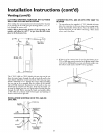
HOT
TEMPERATURE-PRESSURE
RELIEFVALVE
/
DISCHARGE PIPE
(Do not capor plug)
PROVIDE A 6" AIR
GAP BETWEEN THE
END OF THE
DISCHARGE PIPE
AND DRAIN
RELIEFVALVE OPENING
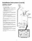
At the time of manufacture, this water heater was provided with a combination tern-
perature-pressure relief valvelisted as complying with the standard for relief valves and
automatic gas shut-off devices for hot water supply systems, ANSI Z21.22. For safe
operation of the water heater, the relief valve must not beremoved from its designated
point of installation or plugged
Your local jurisdictional authorlty, while mandating the use of a temperature-pressure
relief valve complying with ANSI Z2122 and ASME,may require avalvemodel different
from the onefurnished with the water heater.
Compliance with suchlocal requirements must be satisfied by the installer or end user
of the water heater with a locally prescribed temperature-pressure relief valve installed
inthe designated opening in the water heateE
Seemanual heading -"Temperature-Pressure Relief Valves" for installation and mainte-
nance of relief valve, discharge line, andother safetyprecaut;ons
13