


Installation Instructions (cont'd)
IIWARNING
A gaswater heater cannotoperateproperlywithout the cor-
rect amount of air for combustion.Do not installin a con-
finedarea sucha closet,unlessyouprovideair asshownin
the "Locating The New Water Heater" section. Never
obstructthe flowof ventilationair.If you haveanydoubtsor
questionsat all,callyourgascompany.Failureto providethe
properamountof combustionair canresultin afire or explo-
sionand can causeDEATH, SERIOUS BODILY INJUR_,OR
PROPERTYDAMAGE.
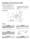
from
any overhang
of Flue
li WARNING
If thiswaterheater willbe usedin beautyshops,barbershops,
cleaningestablishments,or self-servicelaundrieswith dry
cleaningequipment,it isimperativethat the water heater or
water heatersbe installedsothat combustionand ventilation
air be takenfrom outsidetheseareas.Referto the "Locating
The New Water Heater" sectionof this manualand alsothe
latest editionofthe NationalFuelGasCode,ANSI Z223.1,also
referred to as NFPA 54 for specificsprovidedconcerningair
required.
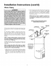
Combustion Air and Ventilation
When determining the installation location for apower vent
water heater, snow accumulation and drifting shouldbe consid-
ered in areas where applicable.
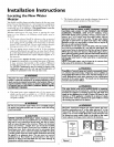
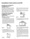
VENTING CLEARANCES
• 0" clearancefor 3" PVC, ABSor CPVC Schedule40 vent piping
fromcombustiblesurfaces.
• 12"minimum from the ground, 18"ceilingoverhangs.Figure2.
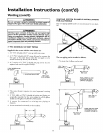
• The PowerVentoutlet terminalshall terminateat least 3 feetabove
any forcedair inletlocatedwithin 10 feet.Figure3a.
• The PowerVentoutlet terminalshallterminate at least4 feetbelow,
4 feethorizontallyfromor 1foot aboveany door,windoworgravity
airinlet into the building.Figure3a.
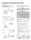
• 18" minimum in all directions from any obstruction that may
interfere.Figure3b.
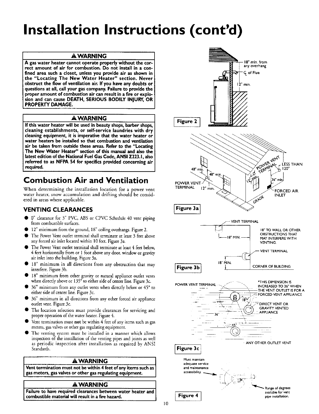
• 18" minimum from other gravityor natural applianceoutlet vents
when directlyaboveor 135° to eithersideofcenterline. Figure3c.
• 36" minimum from any outlet ventswhen directlybelowor 45° to
eithersideofcenter line.Figure3c.
• 36" minimum inall directionsfrom any other forcedair appliance
outletvent. Figure3c.
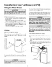
• The location selection must provide clearancesfor servicing and
properoperationof thewater heater.Figure4.
• Ventterminationmust not bewithin 4 feetofany itemssuchasgas
meters,gasvalvesor othergasregulatingequipment.
• The venting system must be installed in a manner which allows
inspection of the installationof the venting pipesand jointsas well
as periodic inspection after installation as required by ANSI
Standards.
iI WARNING
Ventterminationmust not bewithin4 feetofanyitemssuchas
gasmeters,gasvalvesorother gasregulating equipment.
iIWARNING
Failureto haverequired clearancesbetweenwater heaterand
combust b e mater alw resut na firehazard.
10
Figure 2 ]
TERMINAL 12"min.
INLET
Figure 3a]
S VENT TERMINAL
L_ I E" MIN,
[F,gu.3b]
IB" TO WALL OR OTHER
OBSTRUCTIONS THAT
MAY INTERFEREWITH
VENTING.
rF VENT TERMINAL
CORNER OF BUILDING
*THIS DIMENSION IS
POWER VENT TERHINAL _ J_ _\
_ _ INCREASED TO 36" WHEN
__ _-- - _ _" _THE VENT OUTLET IS FOR A
_ _ _j_ FORCED VENT APPLIANCE
_B"*/'
_ _ GRAVITY VENTED
- "- _ ' _ _-DIRECTVENTOR
36,_ _--'- \ _ APPLIANCE
45°
ANY OTHER OUTLET VENT
[Figure3cI
Must maintain
adequate service
and maintenance
ibility.
Rangeof degrees
[ Figure 4 ] available for vent
pipe installation.