


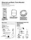
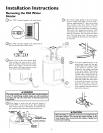
Installation Instructions (cont'd)
Temperature-Pressure
Relief Valve
&WARNING
At the time of manufacture this water heater was provided
with a combination temperature-pressures relief valve certi-
fied by a nationally recognized testing laboratory that main-
tains periodic inspection of production of listed equipment
or materials, as meeting the requirements for Relief Valves
and Automatic Gas Shutoff Devices for Hot Water Supply
Systems, and the current edition of ANSI Z21.22 • CSA 4.4
and the code requirements of ASME. If replaced, the valve
must meet the requirements of local codes, but not less
than a combination temperature and pressure relief valve
certified as meeting the requirements for Relief Valves and
Automatic Gas Shutoff Devices for Hot Water Supply
Systems, ANSI Z21.22, CSA 4.4 by a nationally recognized
testing laboratory that maintains periodic inspection of pro-
duction of listed equipment or materials.
The valve must be marked with a maximum set pressure
not to exceed the marked hydrostatic working pressure of
the water heater (150 Ibs./sq. in.) and a discharge capacity
not less than the water heater input rate as shown on the
model rating plate. (Electric heaters, watts divided by 1000
x 3412 equal BTU/Hr. rate.)
Your local jurisdictional authority, while mandating the use
of a temperature-pressure relief valve complying with ANSI
Z21.22 0 CSA 4.4 and ASME, may require a valve model dif-
ferent from the one furnished with the water heater.
Compliance with such local requirements must be satisfied
bythe installer or end user of the water heater with a locally
)rescribed temperature-pressure relief valve installed in the
designated opening in the water heater in place of the facto-
ry furnished valve.
For safe operation of the water heater, the relief valve must
not be removed from it's designated opening or plugged.
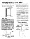
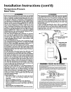
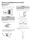
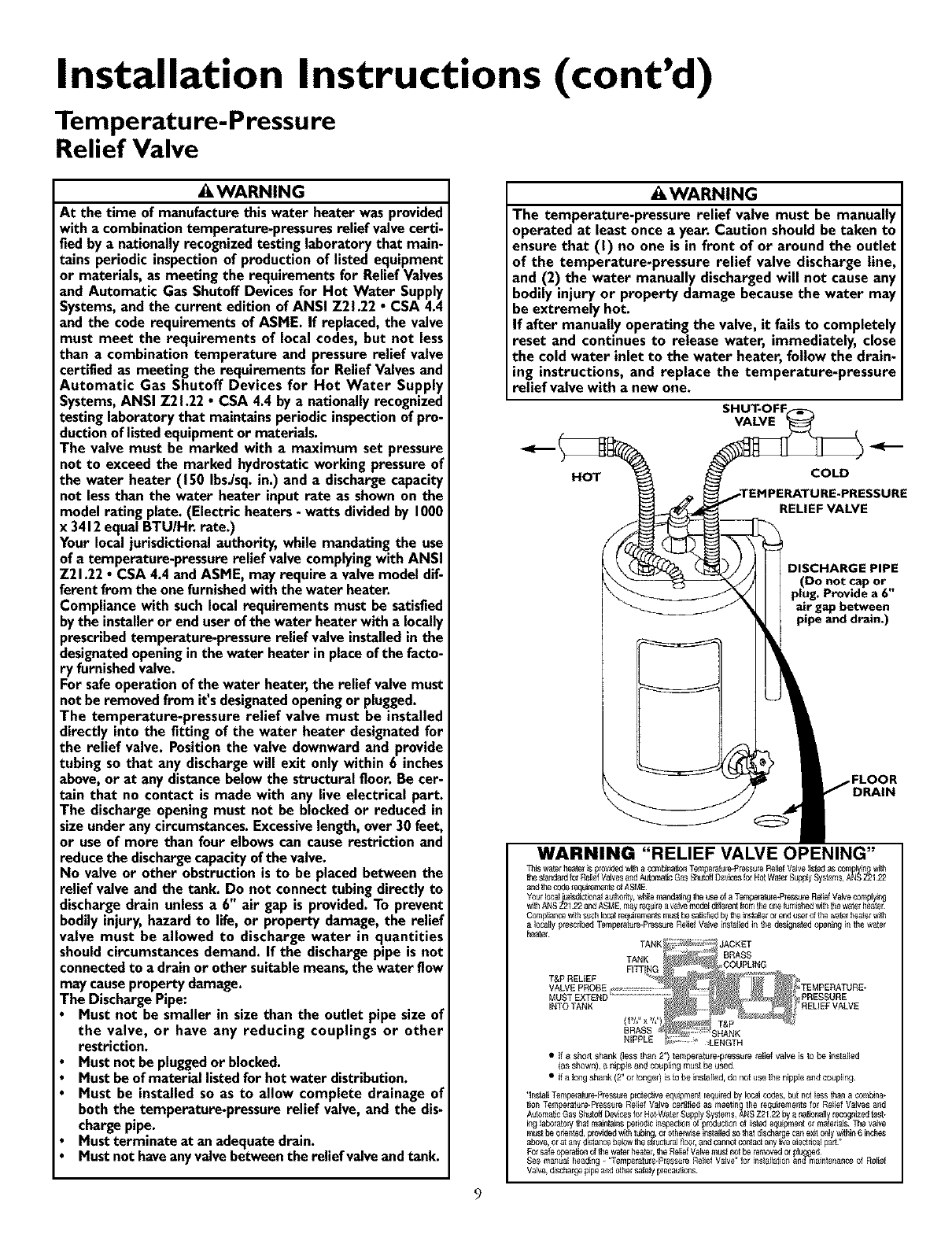
The temperature-pressure relief valve must be installed
directly into the fitting of the water heater designated for
the relief valve. Position the valve downward and provide
tubing so that any discharge will exit only within 6 inches
above, or at any distance below the structural floor. Be cer-
tain that no contact is made with any live electrical part.
The discharge opening must not be blocked or reduced in
size under any circumstances. Excessive length, over 30 feet,
or use of more than four elbows can cause restriction and
reduce the discharge capacity ofthe valve.
No valve or other obstruction is to be placed between the
relief valve and the tank. Do not connect tubing directly to
discharge drain unless a 6" air gap is provided. To prevent
bodily injury, hazard to life, or property damage, the relief
valve must be allowed to discharge water in quantities
should circumstances demand. If the discharge pipe is not
connected to a drain or other suitable means, the water flow
may cause property damage.
The Discharge Pipe:
Must not be smaller in size than the outlet pipe size of
the valve, or have any reducing couplings or other
restriction.
Must not be plugged or blocked.
Must be of material listed for hot water distribution.
Must be installed so as to allow complete drainage of
both the temperature-pressure relief valve, and the dis-
charge pipe.
Must terminate at an adequate drain.
Must not haveany valve between the relief valve and tank.
&WARNING
The temperature-pressure relief valve must be manually
operated at least once a year. Caution should be taken to
ensure that (I) no one is in front of or around the outlet
of the temperature-pressure relief valve discharge line,
and (2) the water manually discharged will not cause any
bodily injury or property damage because the water may
be extremely hot.
If after manually operating the valve, it fails to completely
reset and continues to release water, immediately, close
the cold water inlet to the water heater, follow the drain-
ing instructions, and replace the temperature-pressure
relief valve with a new one.
._(
HOT
VALVE
COLD
LIRE-PRESSURE
RELIEF VALVE
DISCHARGE PIPE
(Do not cap or
plug. Provide a 6"
air gap between
pipe and drain.)
.FLOOR
DRAIN
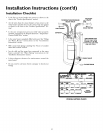
WARNING "RELIEF VALVE OPENING"
11dewatel beateris prowbedw_ha ¢0mb[natbnT_l_lp6emtule_PressureRelbf Valvelisiodas coEy_01y[nlgw_/
thesbe'dafdforReliefValvesa'tl A_lomatbGasShddl OevicestorHotWaterS®#y System& AN$Z2122
aid tie coderedei_le_Ls ofASME
Your10caJiu_odictmn_Jauthe(_y,whilenland_ng tie useofaTemp_ature-PmssureReliefValvecomplying
_ith AN8Z2122 and ASME,mayrequireavalvemodeld_ferentflora theone_rnisbedwiththewatelheater
Com_ian_ withSUChIoca_requile_'_r_smusthe satisfiedbytheins[aHerelenduser oftie watel beaterwith
a locally prescribed TemberaIure,PiessureRelief VaJveinstaJlodin t_ desighated ®ening in thewater
heater
9
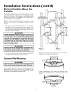
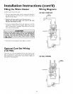
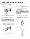
• IfashoIt shank (less lhan 2") temperature*pressure relief ValVeis to be inslalled
(as shown), a nippleand co®ling must be Used
• Ifa longshank (2" or brger) is to be installed, de not use the nipple and co®ling
'Insta_lTer®eralure_Pressuleprotec_veeq_pment redeirodby IocaJcodes, bL4notlessthai a combina*
lien Temperatule.Presst_reRelief V_lve certified as meeting Ibe redeilements for Relief Valves and
AulomaticGas$betdf Deviceslor Hot-WalerSubelySystems,ANSZ2122 by _ nadena_lyrecognizedtest_
_g laboratorytbe_msJntainsperiodb in_on Ofproductionof listed edeipment or matelbJs The valve
must be ortentod,j3iowbedw_thtub_rg,el otbervaseinstsJlodso_at d_scharge•caqex_•only_thin_6 inches
above,orat any dlstaqcebelowthestfuctt_ra_f_oor,aod c_{_ot cont_ any I_veelectnca_part¸
Fol safe®elation of_ waterbealel, _e R_l_efVahtemust notbe removedel _YULqge_J
See manual heading * 'Ternbetature*PressuleRelod V_]ve'r for ins®laden and maintenanceof Relief
Valve,dmcbergepipeard othersafely preeautJ®s