


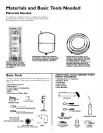
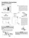

Installation Instructions (cont'd)
Optional Wall Mounting (cont'd)
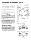
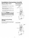
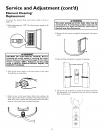
3. Determine the location on the wall, and then the height
above the floor which the wall securing bracket will be
placed. Using adequate screws, or nuts and bolts (not sup-
plied), fastenthe wall securing bracket to the wall.
SECURING SCREW TO
WALL M[N. 12 x _Z,_'
"_"-- "_I (NOT SUPPLIED)
"-I
_ SECURING SCREWTO
WALL MIN. 12x%"
(NOT SUPPLIED)
Water Piping
*A WARNING
HOTTER WATER CAN SCALD: Water heaters are intend-
ed to produce hot water. Water heated to a temperature
vhich will satisfy space heating, clothes washing, dish wash-
ing, and other sanitizing needs can scald and permanently
injure you upon contact. Some people are more likely to be
_ermanently injured by hot water than others. These
include the elderly, children, the infirm, or physically/men.
tally handicapped. If anyone using hot water in your home
fits into one of these groups or if there is a local code or
state law requiring a certain temperature water at the hot
water tap, then you must take special precautions. In addi-
tion to using the lowest possible temperature setting that
satisfies your hot water needs, a means such as a mixing
valve, shall be used at the hot water taps used by these peo-
ple or at the water heater. Mixing valves are available at
plumbing supply or hardware stores. Follow manufacturers
instructions for installation of the valves. Before changing
the factory setting on the thermostat, read the
"Temperature Regulation" section in this manual.
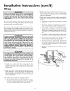
HOT WATER A
OUTLET T
TEMPERED_
WATER OUTL
*MIXING VALVE WATER OUTLET
ON WATER HEATER
COLD WATER
_¢TO COLD WATER
INLET ON
WATER HEATER
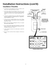
If a water heater is installed in a closed water supply system;
such as one having a back-flow preventer, check valve, water
meter with a check valve, etc.., in the cold water supply; means
must be provided to control thermal expansion. Contact the
local utility or SearsServiceCenter on how to control thissituation.
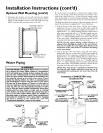
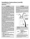
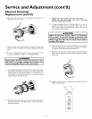
The illustration showsthe attachment ofthe water piping to thewater
heater. The water heater isequipped with _" water connections.
• Look at the top of the water heater. The hot water outlet is
marked hot. Put two or three turns of teflon tape around the
threaded end of the compression coupling and around the _"
threads of the 5_"x ½"reducer bushing. Put two or three turns of
teflon..... tape around both ends,of a Vd'threaded_,, nip le (not.sup-
plied in the mstallauon kit). Attach the Z threa_ed topple to
the _" x }_"reducer bushing and screw into the hot water outlet
of the water heater. Using flexibleconnectors, connect the hot
water pipe to the hot water outlet ofthe water heater.
NOTE: If using copper tubing, solder tubing to an
adapter before attaching the adapter to the water connec-
tions. Do not solder the water supply lines directly to the
connections of the water heater. It will harm the fittings
on the water heater.
Look at the top of the water heater. The cold water inlet is
marked cold. Put two or three turns of teflon tape around the
threaded end of the compression coupling and around the _"
threads of the 5_"x ½"reducer bushing. Put two or three turns of
teflon..... tape around both ends,of a Vd'threaded_,, nip_jple(not.sup-
plied m the mstallauon kzt). Attach the Z threaded topple to
the _" x Vd'reducer bushing and screw into the cold water inlet
of the water heater. Using flexibleconnectors, connect the hot
water pipe to the hot water outlet oftile water heater.
NOTE: Your water heater is insulated to minimize heat
loss from the tank. Further reduction in heat loss can be
accomplished by insulating the hot water lines from the
water heater.
Installation COMPLETED using
Installation Kit
SHUT-OFF
1/2" x314" REDUCER_ _ 1/2" x3/4" REDUCER
BUSHING BUSHING
1/2 THREADED_ _,_ _1/2 THREADED
NIPPLE (not supplied _ ..--_Y_ ...... _ NIPPLE (not supplied
with installation kit) /_--_-_-J_-_ _ "\with installation kit)
-----¢.1