


368262-UIM-B-1008
Johnson Controls Unitary Products 7
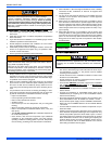
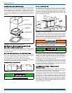
All six suspension points must be level to ensure proper and quiet fur-
nace operation. When suspending the furnace, use a secure platform
constructed of plywood or other building materials secured to the floor
or ceiling joists. Refer to Figure 11 for details and additional informa-
tion.
When moving or handling this furnace prior to installation, always leave
the doors on the furnace to provide support and to prevent damage or
warping of the cabinet. When lifting the furnace, support the ends of
the furnace rather than lifting by the cabinet flanges at the return air
openings (bottom or sides) or supply air opening.
It is acceptable to use the primary heat exchanger tubes as a lifting
point provided that the tubes are lifted at the front of the heat exchang-
ers where attached to the vestibule panel. Do not use the top return
bend of the heat exchangers as lifting points as the tubes may shift out
of position or their location brackets/baffles.
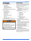
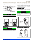
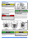
DOWNFLOW APPLICATION
To apply the furnace in a downflow position, it will be necessary to
rotate the vent blower 90° left or right so that the vent pipe passes
through the side of the furnace casing rather than the end. See Figure
6.
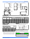
COIL INSTALLATION COIL/FURNACE ASSEMBLY - MC/FC/PC SERIES
COILS
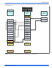
FIGURE 5: Typical Suspended Furnace / Crawl Space Installation
During installation, doors must remain on the furnace when
moving or lifting.
Support
Rod
Support
Angle (x3)
Maintain 6” minimum
clearance between support
rods and front of furnace
For modulating furnaces to be used in the downflow position, it is
necessary to rotate the gas valve so that it is upright when the fur-
nace is installed. Loosen the pipe union between the gas valve and
manifold, rotate the valve as far upward as it will go, and tighten the
union. See Figure 7.
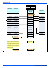
FIGURE 6: Downflow Venting FIGURE 7: Downflow Installation - Gas Valve Rotation
LEFT SIDE VENT
RIGHT SIDE VENT
Rotate vent
blower 90°
either way
For downflow
installation,rotate
gas valve upwards,
as shown
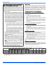
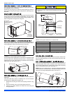
On all installations without a coil, a removable access panel is rec-
ommended in the outlet duct such that smoke or reflected light
would be observable inside the casing to indicate the presence of
leaks in the heat exchanger. This access cover shall be attached in
such a manner as to prevent leaks.
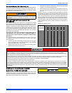
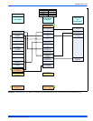
FIGURE 8: Vertical Applications (Typical)
UPFLOW
DOWNFLOW
Furnace
Furnace